Blog Layout

Tips for Successful Seal Installation

Cliff • June 25, 2019

The success or failure of a seal design is often dependent on how the seal was installed. There are many seals that easily slip into glands with simple installation procedures. But when installing seals with any volume, it’s important to have an established method to ensure consistent performance of the seal. 

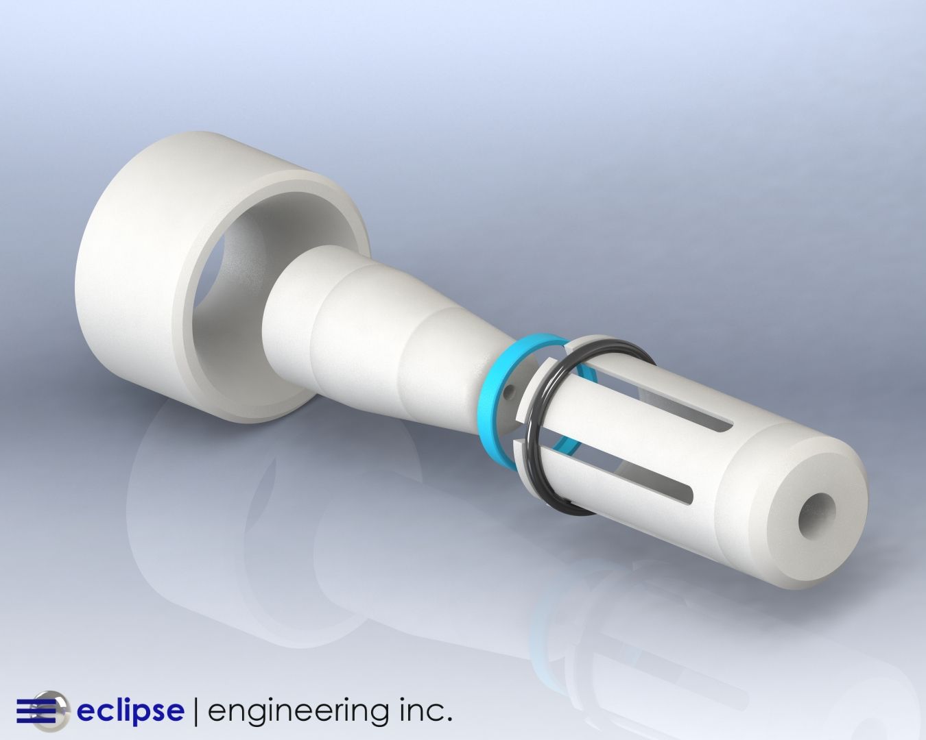
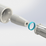
We were recently asked to design installation tools for a 2-011 O-ring. At first glance, we would normally achieve this simply by using our hands. But when faced with 150,000 pieces, installation becomes fatiguing, O-rings get rolled rather than stretched in the gland, and the possibility of spiral failure over a large number of pieces becomes an eminent issue.

In this case, we chose to use a bullet which allowed the O-ring to pass over part of the installation that would tear the rubber. We also used an approved lubricant and a specially-designed pusher tool. The set was designed with ergonomics as a primary consideration to ensure that assembler fatigue did not become an issue.

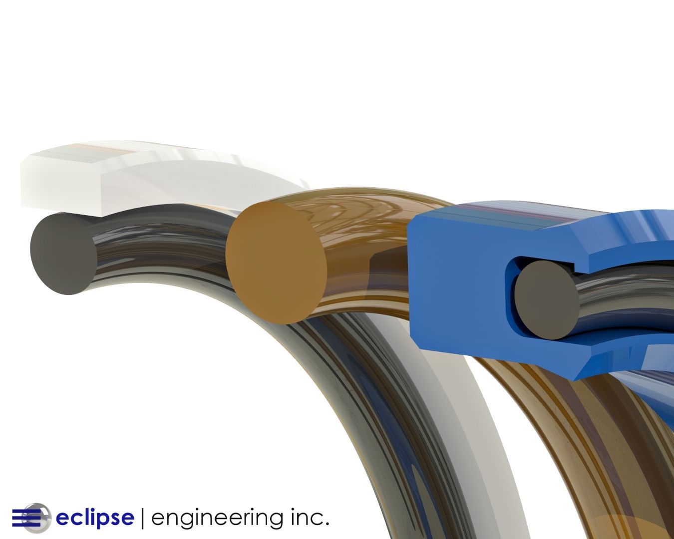
An O-ring is a very simple case because it can easily be deformed to go into very small rod glands, and fit into most piston glands.

As a seal designer in polymers such as Teflon , Polyurethane, and rigid plastics like PEEK or Torlon require a change in the design characteristics to allow for installation. This can include special tools to aid in insertion, or special seal glands for ease in installation.

We typically avoiding polymers like Teflon because they often create the greatest challenges. As designers, considering installation into solid glands is an integral part in selecting a cross-section, along with the operating parameters of the application.

Specialized Installation Tools for Seals

Most PTFE blends will have elongations in excess of 100%, so using standard bullet tools over the piston along with pusher rings is a standard in the industry. These tools are easily designed and manufactured to allow the operator to push the ring over the OD of the piston.

A resizing tool is necessary to remove most of the stretch induced in the ring, and to re-size the seal so that it can be forced into the bore diameter. Some very thin cross-section rings may be installed in small volume by hand if sufficient care is given to not tear the ring. But a resizing tool is usually necessary to complete the installation.

With any volume, installation tools will ensure the seal is seated in the gland without damage.

Using screw drivers and other such tools will mar or damage the PTFE, so these should never reach the assembly table. In some cases dental floss can be used, if the cross-section is small enough and then resized into the gland.

In the case of Urethane or other polymers that exhibit some elasticity, the seal can often be stretched into the gland. While the possibility of marring the surface is less prevalent, care should still be taken not to damage the sealing surfaces of the seal.

Some of the piston-style Urethane rings may have very heavy cross sections, and the use of installation tools as described above is recommended.

Considerations for Installing Small Rod Glands

Rod glands, especially those with very small diameters, create a different set of installation problems. Looking first at O-rings, if you can reach into the gland, it’s usually very easy to slip one edge of the O-ring in the groove, and for rest of the O-ring to comply.

If the groove is too deep, or the diameter is too small to reach in, then a three-pronged tool can be used to deform the ring into a kidney shape, slide the seal into the rod bore, catch an edge and withdraw the tool. You would then use either an ID resizer tool or plastic probe to insure the seal is properly seated into the gland.

A Teflon ring will generally require turning the part into a kidney shape either in your hand or with the use of a three-pronged tool, and then sliding the seal into the seal groove and withdrawing the tool. In the case of Teflon-style rings, it’s often required that an ID resizing tool is required to gently massage the ring back to it’s round shape removing the bends produced by putting it into a kidney shape.

Tricks to Successful Seal Installation

For polymers like PTFE or Teflon, heat is powerful in softening the material to make it more pliable. The rings usually need be heated up to several hundred degrees.

Boiling water in a microwave is an effective way to soften the ring. The rings will cool very quickly, so application must be done immediately.

Where lubrication is allowed, this can often help the more elastic seals find their way. This can also be helpful even for Teflon. The only issue in the use of lubricants is that your fingers are now lubed as well.

In the process of resizing, we often put assemblies with seals on them in the freezer to help them collapse down, then install them into a bore.

Our Seal Installation Process

We are often asked to aid in developing an installation technique. We normally start with the tricks just to see what’s possible. But in general, the development of a set of installation tools normally ensures a repeatable assembly process, with no damage to the seal.

We normally design a set of tools for one application, and rarely make more than one set. This alone drives the cost of tools and why we often avoid them. However, when you consider the time spent without the proper tooling and the possibility for damaging the seal, it can be an inexpensive solution in the long run.

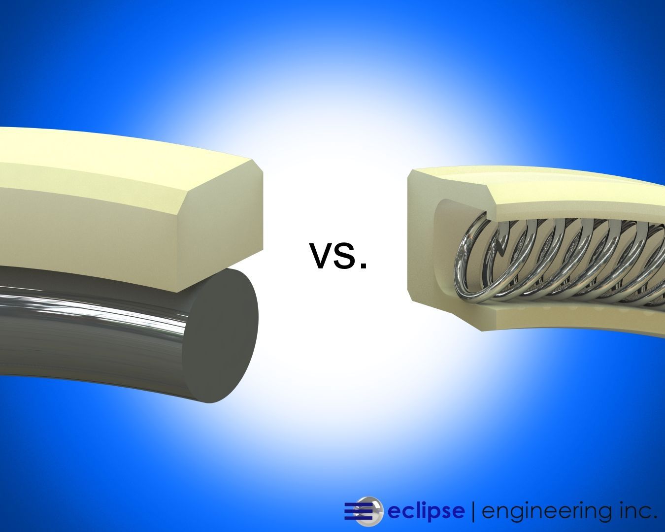
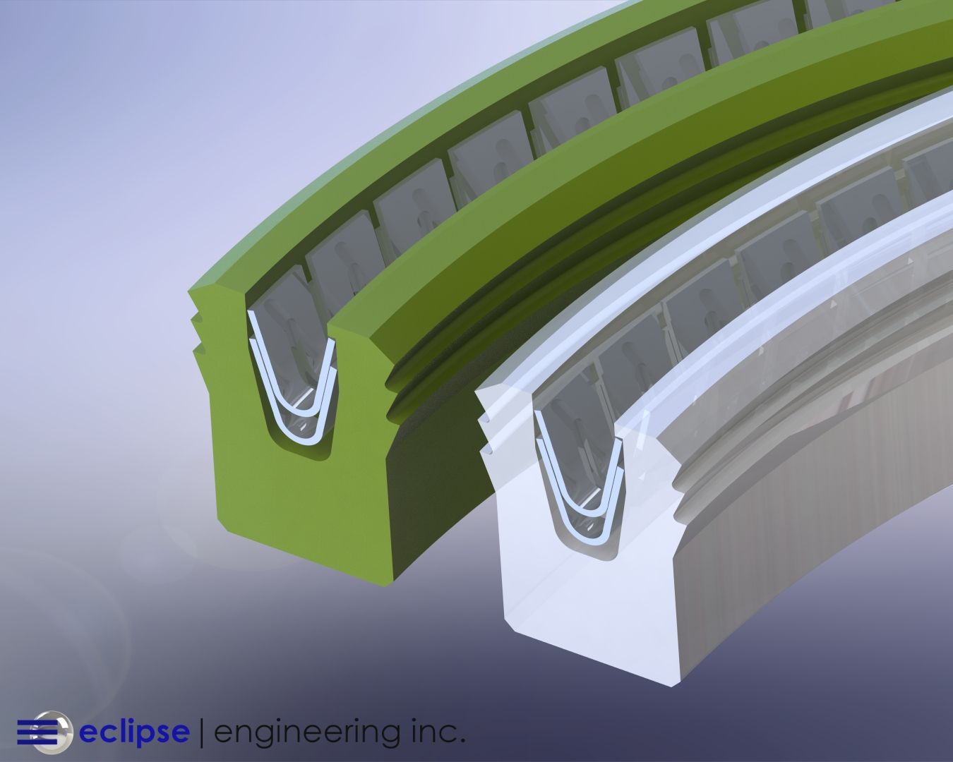
We didn’t discuss installing Spring energized seals in solid glands because this is rarely done due to how easy it is to damage the lip or deform the cross section. This can be done in rare cases, but typically the seal is installed into two-piece or stepped glands.

Eclipse designs and manufactures installation tools for most seal applications, as well as taking a customer’s hardware and designing methods for installation. We are constantly improving tools and methods for installation.

We are also always looking for ways to improve our customer service and lead-times. Discover how we maintain minimal lead time with every seal »

By Doug Montgomery February 13, 2025
Learn how Eclipse Seal’s custom spring energized ball seats with angled grooves improve performance
By Doug Montgomery January 17, 2025
Eclipse deals regularly with challenging sealing applications from all industries. High pressures and speeds create unique sets of conditions where seal design and material properties are pushed to the limit. While reciprocating applications can certainly test seals to the edge of capability, often times rotary applications can present the greatest challenge to seal integrity and wear life. Unlike reciprocating configurations where the seal is acting on a different part of the shaft or bore throughout it’s operating range, rotary seals must operate on the same sealing area continuously. This makes things like heat rejection much more difficult, especially in unlubricated or dry running applications. Extreme localized heating can have negative affect on both seal and hardware life. Rotary applications also pose sealing difficulties due to the simple fact that surface speeds can be much higher than in reciprocating systems. A simple electric motor can operate at very high rpm, while long stroke, high speed reciprocating machinery is a major piece of equipment that is far less common (though Eclipse also has sealing solutions in a number of these situations). A customer approached Eclipse with an application that was beyond the scope and capability of any standard, off-the-shelf rotary seal. This sealing system would require a combination of both wear resistance in high-speed rotary, as well as excellent leakage control and sealability. Two factors that, more often than not, work in opposition to each other. The Customer Issue The customer was developing a test system that required an electric motor shaft passed through the wall of a large vacuum chamber. The testing apparatus needed a sizable motor to meet the speed and torque requirements. Adapting the motor to operate inside the chamber would not be practical due to contamination and motor cooling concerns. Therefore, the motor would have to be placed outside the chamber and a driveshaft would have to go through the chamber wall. Which, of course, would need a seal. Operating Conditions:
 Rotary Shaft Seal
 Shaft Diameter: 2.5”
 RPM: 7,500 RPM - unlubricated
 Pressure: Vacuum internal side / 1 ATM external side Temperature: 40° - 90°F The customer knew any kind of off-the-shelf rotary seal with a rubber element would not last any amount of time in the combination of speed and a dry running condition. They also knew a single lip PTFE seal would likely not meet their leakage requirements. Therefore, they turned Eclipse for a custom sealing solution.
By Doug Montgomery November 25, 2024
Eclipse has engineered sealing solutions for applications all over the planet and in a plethora of environments. From the bottom of the ocean to orbiting the earth, Eclipse is challenged by the unique conditions in each application. Whether it be extreme temperature and pressure or severely caustic or abrasive media, Eclipse has a solution for most every sealing problem. One distinct environment presents a particularly challenging set of circumstances for seal design – high radiation. Eclipse’s primary seal material choice for many applications is PTFE and PTFE blends. With all the wonderful attributes PTFE possesses as a seal material, radiation resistance is not one. In high radiation environments PTFE’s properties can degrade to essentially rule it out as a suitable material. The options for effective sealing materials that are also radiation resistant becomes very limited. The seal designer is therefore confronted with creating a seal that is expected to perform in every way a typical PTFE seal operates, out of materials that are not as favorable to sealing. This is where Eclipse’s engineering experience and expertise in seal design come to the forefront. The Client's Issue Eclipse was approached by a customer that was looking for a seal solution for a sensor used in a nuclear application. It would be operating in an environment with both high temperature and high Gamma radiation. Operating Conditions:
 Reciprocating Rod Seal
 Rod Diameter: Ø1.000
 Stroke: 1.5”
Cycle Rate: 2-4 cycles per minute
 Media: Air, Salt Water Mist
 Pressure: 100 PSI
 Temperature: 70° to 450°F
 Gamma Radiation Exposure: 10^6 rads
By Doug Montgomery November 14, 2024
Technological advancements in the area of robotics have led to more and more life-like creations existing only in works of science fiction a few decades ago. Development in autonomous logic processing and sensing allows bipedal robots to walk over uneven ground, up and down stairs, open doors and carry loads. Fast response to dynamic and unpredictable real-world environments is critical for the future use of robots in true-life service and practical employment in the years to come. While software and sensor development remain the primary focus of most research, the physical mechanics of next-gen robotics are also continually progressing. Physical components and control systems such as hydraulic pumps and cylinders, servo motors, and structural members are under pressure to continually be lighter, stronger, more efficient and less expensive. Increased demands on the physical components facilitate the need for innovative solutions in design and material usage. Advancements in construction and technology have spilled into all areas of robotic mechanisms and the many seals located throughout the system need to meet the challenges of tomorrow. Eclipse has been at the forefront of this research and has developed innovative solutions pushing the boundaries of conventional sealing devices. MicroLip™ by Eclipse is a prime example of most demanding applications forging new technologies in the sealing world. The Client's Issue Eclipse was approached by a leading robotics company looking for a sealing solution operating under a challenging set of conditions. While many components of tomorrow’s robotics are now controlled and actuated by servo/stepper motors and various electronic devices, the heaviest and most powerful movements are still driven by traditional hydraulics. The constant demand for more powerful hydraulic actuation in ever deceasing size and weight requirements has put tremendous strain on component design. But if robots are to progress to the point where they are usefully employed in the world, high power in a compact design is necessary. A robot, for example, used to survey and assist in a disaster zone too unstable for normal rescuers, must fit through doorways and over obstacles yet still be physically strong enough to render assistance. Large hydraulic systems are capable of moving extremely heavy loads but size and weight constraints of a humanoid size robot limit potential. The robot’s internal power supply to drive all components is also a limiting factor. Our client was developing a new hydraulic pump to drive all major motion aspects of their robotic systems. Their main objective was to minimize the pump’s physical size as much as possible while increasing output and improving power consumption efficiency. This means higher pressures and speeds on increasingly smaller and lighter components. Application Parameters: Shaft Diameter: Ø9.5mm Seal Housing Envelope: 5mm radial cross-section by 6mm axial width Rotational Speed: 3,500 RPM nominally; 6,000 RPM max Operating Pressure: 125 PSI min, 225 PSI nominal, 350 PSI max Surface Finish: 0.04µm Media: Hydraulic Oil While the above combination of pressure and speed might present difficulties for any conventional seal alone, the client’s extremely small physical envelope to house the seal further complicated the matter. If that wasn’t enough, the application presented the additional sealing challenge of up to 0.003” [0.08mm] of shaft runout. As part of the downsizing of all components in the pump, shaft support bearings were minimized leading to the possibility of runout. The wobbling effect of the shaft creates problems as the sealing lip has follow a moving, uneven mating surface, therefore potential leak-paths are created. Wear life can also be compromised due to higher concentrations of uneven loads. The combination of high pressure, high speed, high runout and minimal gland size present a worst-case scenario for a typical seal. Unsurprisingly, the client faced leakage of hydraulic fluid after only short periods of service with any conventional seal they had tested. Eclipse knew the had the perfect solution for this application. One developed to handle such extreme rotary sealing conditions: MicroLip™.
Share by: