3 Common Types of Backup Rings and Their Uses
The Backup ring likely found its roots in the use of leather packings, where leather was used as the sealing device in glands prior to the use of O-Rings.
The O-ring provided a much better seal compared to leather. However, the leather often filled the extrusion gap allowing for larger gaps.
The persistent problem that engineers faced was how to take an O-ring that operated optimally in close extrusion gaps, and extend its service with widening extrusion gaps.
The answer was the Backup ring.
The first Backup ring devices were made from materials like leather.
Leather did two things to help the O-Ring: it filled the gap, and continued to lubricate the O-Ring during dry running conditions. You can still occasionally find some old style hydraulic systems using leather back-up rings.
Modern Construction of the Backup Ring
Our modern hydraulic systems often find O-rings operating at extreme pressures, with the use of Backup rings made from a variety of materials like Teflon® or filled PTFE materials.
Polyester Elastomers like Hytrel®, Nylon , PEEK , and other high modulus materials that are compatible both in pressure and temperature to the application.
These Backup ring devices can take on many forms such as solid rings, split rings and spiral wound Backup rings.
Where there are extreme pressures and high temperatures you may find cammed Backup rings with varying materials to protect the O-ring, while at the same time closing the extrusion gap allowing extreme pressures in excess of 100 KPSI (690 KPA).
3 Common Backup Ring Shapes
There are 3 basic standard shapes for Backup rings: Solid Backup Rings, Spiral Wound Backup Rings and Scarf Cut Backup Rings.
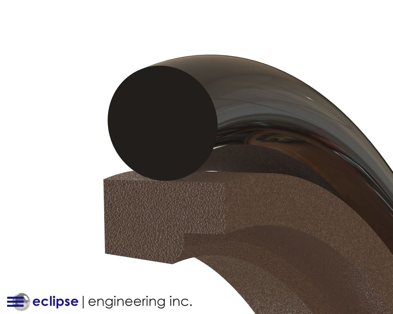
Solid Backup Ring

The Solid Backup ring which, when made of an appropriate material can be forced into solid rod glands, but must be stretched to go into piston glands.
Face seals often find solid Backup rings due to the ease of installation.
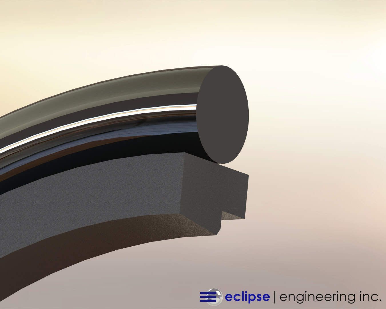
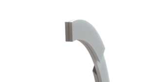
Scarf Cut Backup Ring

The Scarf Cut Backup ring is probably the most commonly used Backup ring in today’s modern hydraulic system.
It’s easy to install in solid glands, whether they’re rod or piston. And because it’s split, the Scarf Cut Backup ring can be made of very hard materials to handle extreme pressures.
A note of caution with very high modulus materials: the split can cause nibbling of the O-Ring allowing for premature failure of the sealing system.
In the event of the need for these higher modulus materials, a softer ring may be placed between the O-Ring and the high modulus ring to protect the O-ring from this nibbling.
When applied properly, the Split Backup ring can open or spread to completely fill the extrusion gap when under pressure — something the Solid ring is unable to do.
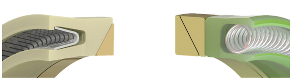
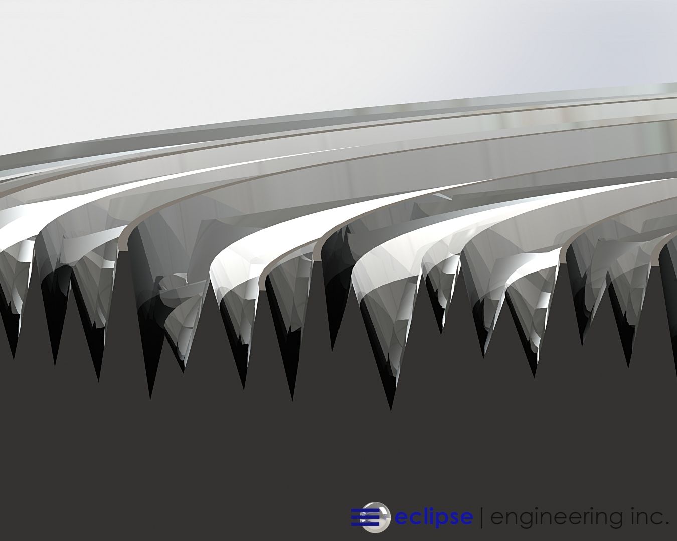
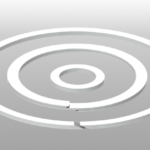
Spiral Wound Backup Ring
The third Backup ring type is the Spiral Wound.
Modern systems rarely use this type of Backup ring due to the cost and availability. The Spiral Wound Backup ring isn’t commonly found on the shelf, but is occasionally employed for specific purposes.
There are many variations on Spiral Wound Backup ring, device such as the Par-Bak® or Cam-bak, which each serve a more specialized need.
Common Uses of Backup Rings.
The necessity of a backup ring is dependent on the extrusion gap, pressure, and temperature of the system.
Most O-rings from the zero series through the 400 series will survive with gaps ranging from .002 to .007 diametrical.
A typical O-ring will perform within the range of extrusion gap, and series up to 1500 PSI (10 MPA).
An extrusion gap allows for manufacturing to put together a system. Generally, the larger the diameter, the larger the extrusion gap.
Tight tolerance cylinders can be difficult to assemble, especially if you’re trying to maintain very small E-gaps.
Backup rings allow for ease in manufacturing to assemble without the fear of damaging rods or bores during the installation process do to overly tight E-gaps.
Cylinders and valve bodies often use O-Rings as static seals. Pressures exceeding 1500 psi and extrusion gaps exceeding the recommended maximum will require some form of back up ring device.
The shape and material will depend on the pressures and temperatures that the system is operating.
In piston style glands where pressure can be seen from both sides of the O-Ring, it’s common to use two Backup rings to support the O-ring in the extrusion gap from both sides of the O-Ring gland.
Static Face Seals often require Backup rings to support O-rings from entering the extrusion gap.
In extreme pressure cycles a known extrusion gap can be enlarged due to the gland bowing or moving into the extrusion gap.
Under extreme pressures, a Cam-style backup ring Is often used to drive a high modulus material into the ever-expanding extrusion gap closing the gap to zero and allowing the rubber O-ring to fill the void without entering the extrusion gap.