Blog Layout

The Ultimate Guide to Seal Glands for Any Project

Doug • October 21, 2021
Spring Energized Seal, Piston Seal, Stepped Gland, Canted Coil Spring

While seal performance, leakage control, and wear-life characteristics are frequently discussed, one critical aspect of a successful sealing system is often overlooked — how a seal is contained in the hardware.  

Whether you want to call it a gland or a groove, the physical space for housing a seal is an important part of the system’s performance. The type of gland greatly dictates the ease and even the possibility of seal installation. Certain seals demand specific gland types, so it’s essential to take these requirements into account.  

Below we’ll discuss the most common types of rod and piston glands and what seals work best for each one.  

Solid Glands  

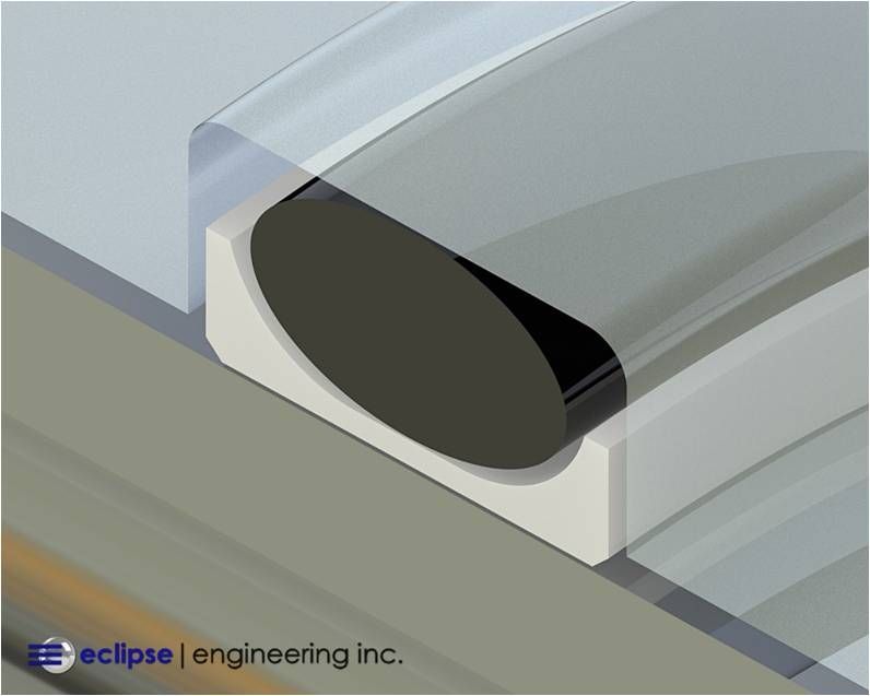
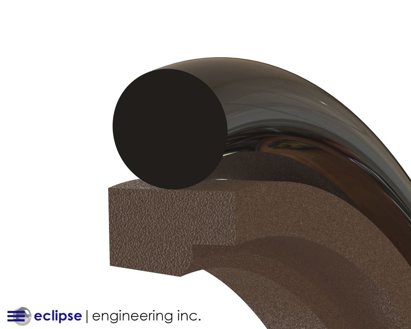
The solid gland is the simplest way to contain a seal. It consists of nothing more than a rectangular groove cut in a housing or piston. Solid glands are prevalent throughout the industry because they’re mostly commonly used to contain  O-Rings .  

Solid glands work fantastic for O-Rings because they count on the elasticity of the O-Ring for installation. Stretching an O-Ring into a groove on a piston is usually a simple process.   

Switch to a much harder and much less elastic material such as  PTFE  and the task can become quite difficult. PTFE seals such as Eclipse’s  ESR Seal Rings  and  EDS Channel Seals  are designed to work in solid glands in conjunction with an O-Ring. This doesn’t mean however, that installation will be trivial.  

In the case of piston configurations, the PTFE seal will need to be stretched to be installed into the groove. This can become quite difficult with larger cross-section seals. Special installation tools may be required to evenly stretch and push the seal without damaging it.   

Once in the groove, the seal will likely need to be resized to be properly seated. This is due to the inelastic nature of PTFE. Higher modulus materials such as  UHMW  can be even more challenging.  

In rod seal configurations, a PTFE seal will need to be folded in on itself to make it small enough to be placed in the groove. In a process often called “kidney beaning,” the seal is folded as gently as possible to avoid any hard creases which can permanently damage the seal.  

Ease of seal installation into a solid gland can be very dependent on the diameter of the seal. At very small diameters it may not even be possible. You should also consider the difficulty of removing seals from solid glands. This often can’t be done without damaging the seal.  

Spring Energized Seals  are generally never recommended to be used in solid glands. The geometry of the seal jacket contributes to the rigid nature of the PTFE and the risk of yielding or damaging the spring is very high.   

Though in some special cases it is possible (like a small cross-section spring going into a large diameter rod gland) but compromises in seal performance and longevity are needed to facilitate this.  

Open Glands  

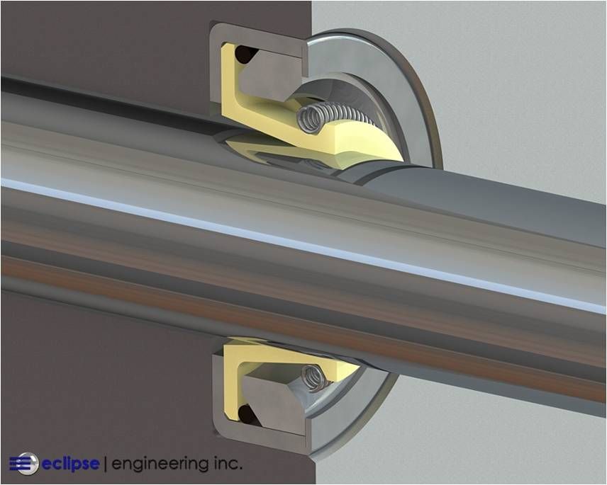
Open glands are essentially a counter-bore in the face of a hardware surface. Since one side of the gland is open, they’re typically reserved for seals with metal cases. The case OD is designed to be slightly over-sized compared to the groove diameter facilitating a light press fit.  

The press fit on the case holds the seal in place. Seals without a case have the potential and tendency to “walk-out” of open glands, even in pure rotary applications. Therefore, products like  Rotary Lip Seals Cased Spring Energized Seals , and  MicroLips  are best suited for open glands.  

Split Glands   

Split or 2-piece glands consist of an open gland with some means of mechanically closing off the open side once the seal is installed. This is commonly accomplished by a simple cover-plate affixed by a bolt pattern.  

Split glands offer many advantages. Seal installation becomes as simple as possible with many cases being a “drop in” procedure. Without having to manipulate or contort the seal or use any specialized installation tooling, risk of damaging a seal during installation is largely mitigated.  

Removing and replacing a worn-out seal also becomes a straight-forward affair. Seals in high-wear applications that need to be replaced regularly or seals that need to be serviced in the field will greatly benefit from the uncomplicated split gland.  

With spring energized seals in critical gas sealing applications and cryogenics, hardware surface finishes typically need to be highly polished for the best control leakage. The split gland makes the polishing procedure in the groove easier since the gland is open.  

The main drawback to the split gland is that it requires extra hardware components and fasteners. Not all hardware configurations present uncomplicated ways to split the gland. This is especially true when redundant seals are needed. Solutions such as a seal carrier group can potentially help. Glands can also be closed by using snap-rings in certain situations.  

Despite possibly adding complexity to the hardware, some sealing solutions will have no other option but to require a split gland. Very small O-Ring energized seal rings and many spring energized seals cannot be installed in any other gland type without damaging the seal.  
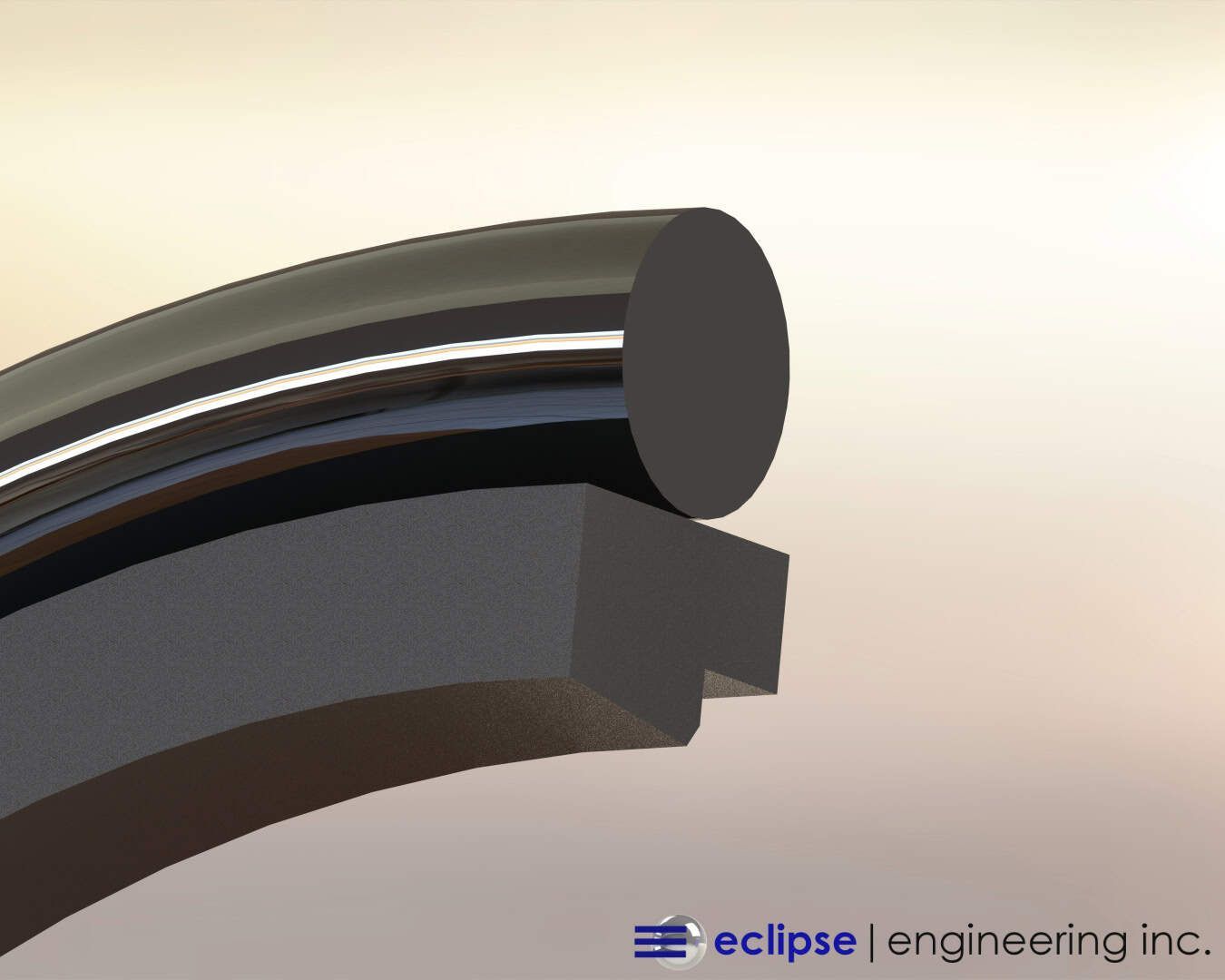
Stepped Glands

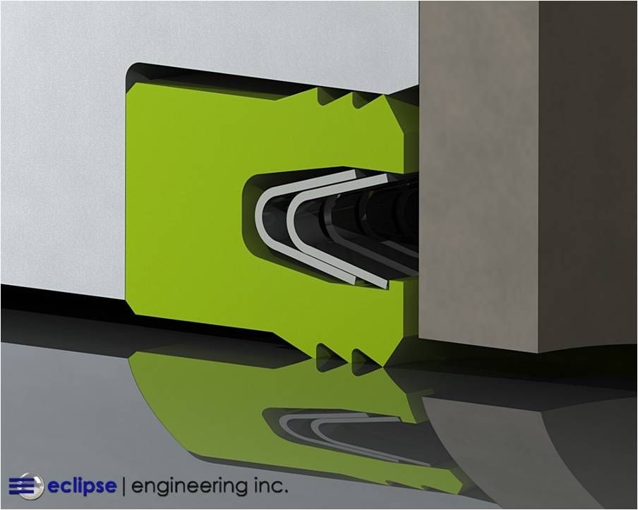
In certain situations, spring energized seals can utilize what’s known as a stepped gland. This is basically an open gland that has a small step or barb that retains the seal on the open side. The seal will need to be installed heel first and the lip will need to be the scraper style to lock in behind the step.  

The height of the step will vary depending on seal cross-section and spring size, but it’s usually 0.020” or less. This is all that’s needed to retain the seal, even in demanding fast reciprocating applications. In fact, once installed the seal will be very difficult to remove without damage.  

Stepped glands allow for easy seal installation but don’t add any extra hardware components like a split gland. This is the chief advantage of the stepped gland. It’s often employed in piston seal applications where keeping the piston a “1-piece” design is highly desirable.  

The stepped gland is relatively difficult to machine in the hardware compared to the other gland types. Small details like chamfers and tool radii need to be carefully controlled to achieve the proper gland dimensions and functionality.  

Eclipse is Here to Help  

How a seal actually gets put in the hardware is a critical aspect that sometimes gets overlooked. Seal gland requirements can have a large impact on the hardware assembly procedure and overall design.   

At Eclipse we have much more than your standard catalog recommendations to offer.  

Some of Eclipse’s greatest engineering challenges have centered around seal installation and gland requirements. Eclipse is here to utilize our decades of seal design and manufacturing experience to help specify the best seal and gland configuration for your application.  

By Doug Montgomery February 13, 2025
Learn how Eclipse Seal’s custom spring energized ball seats with angled grooves improve performance
By Doug Montgomery January 17, 2025
Eclipse deals regularly with challenging sealing applications from all industries. High pressures and speeds create unique sets of conditions where seal design and material properties are pushed to the limit. While reciprocating applications can certainly test seals to the edge of capability, often times rotary applications can present the greatest challenge to seal integrity and wear life. Unlike reciprocating configurations where the seal is acting on a different part of the shaft or bore throughout it’s operating range, rotary seals must operate on the same sealing area continuously. This makes things like heat rejection much more difficult, especially in unlubricated or dry running applications. Extreme localized heating can have negative affect on both seal and hardware life. Rotary applications also pose sealing difficulties due to the simple fact that surface speeds can be much higher than in reciprocating systems. A simple electric motor can operate at very high rpm, while long stroke, high speed reciprocating machinery is a major piece of equipment that is far less common (though Eclipse also has sealing solutions in a number of these situations). A customer approached Eclipse with an application that was beyond the scope and capability of any standard, off-the-shelf rotary seal. This sealing system would require a combination of both wear resistance in high-speed rotary, as well as excellent leakage control and sealability. Two factors that, more often than not, work in opposition to each other. The Customer Issue The customer was developing a test system that required an electric motor shaft passed through the wall of a large vacuum chamber. The testing apparatus needed a sizable motor to meet the speed and torque requirements. Adapting the motor to operate inside the chamber would not be practical due to contamination and motor cooling concerns. Therefore, the motor would have to be placed outside the chamber and a driveshaft would have to go through the chamber wall. Which, of course, would need a seal. Operating Conditions:
 Rotary Shaft Seal
 Shaft Diameter: 2.5”
 RPM: 7,500 RPM - unlubricated
 Pressure: Vacuum internal side / 1 ATM external side Temperature: 40° - 90°F The customer knew any kind of off-the-shelf rotary seal with a rubber element would not last any amount of time in the combination of speed and a dry running condition. They also knew a single lip PTFE seal would likely not meet their leakage requirements. Therefore, they turned Eclipse for a custom sealing solution.
By Doug Montgomery November 25, 2024
Eclipse has engineered sealing solutions for applications all over the planet and in a plethora of environments. From the bottom of the ocean to orbiting the earth, Eclipse is challenged by the unique conditions in each application. Whether it be extreme temperature and pressure or severely caustic or abrasive media, Eclipse has a solution for most every sealing problem. One distinct environment presents a particularly challenging set of circumstances for seal design – high radiation. Eclipse’s primary seal material choice for many applications is PTFE and PTFE blends. With all the wonderful attributes PTFE possesses as a seal material, radiation resistance is not one. In high radiation environments PTFE’s properties can degrade to essentially rule it out as a suitable material. The options for effective sealing materials that are also radiation resistant becomes very limited. The seal designer is therefore confronted with creating a seal that is expected to perform in every way a typical PTFE seal operates, out of materials that are not as favorable to sealing. This is where Eclipse’s engineering experience and expertise in seal design come to the forefront. The Client's Issue Eclipse was approached by a customer that was looking for a seal solution for a sensor used in a nuclear application. It would be operating in an environment with both high temperature and high Gamma radiation. Operating Conditions:
 Reciprocating Rod Seal
 Rod Diameter: Ø1.000
 Stroke: 1.5”
Cycle Rate: 2-4 cycles per minute
 Media: Air, Salt Water Mist
 Pressure: 100 PSI
 Temperature: 70° to 450°F
 Gamma Radiation Exposure: 10^6 rads
By Doug Montgomery November 14, 2024
Technological advancements in the area of robotics have led to more and more life-like creations existing only in works of science fiction a few decades ago. Development in autonomous logic processing and sensing allows bipedal robots to walk over uneven ground, up and down stairs, open doors and carry loads. Fast response to dynamic and unpredictable real-world environments is critical for the future use of robots in true-life service and practical employment in the years to come. While software and sensor development remain the primary focus of most research, the physical mechanics of next-gen robotics are also continually progressing. Physical components and control systems such as hydraulic pumps and cylinders, servo motors, and structural members are under pressure to continually be lighter, stronger, more efficient and less expensive. Increased demands on the physical components facilitate the need for innovative solutions in design and material usage. Advancements in construction and technology have spilled into all areas of robotic mechanisms and the many seals located throughout the system need to meet the challenges of tomorrow. Eclipse has been at the forefront of this research and has developed innovative solutions pushing the boundaries of conventional sealing devices. MicroLip™ by Eclipse is a prime example of most demanding applications forging new technologies in the sealing world. The Client's Issue Eclipse was approached by a leading robotics company looking for a sealing solution operating under a challenging set of conditions. While many components of tomorrow’s robotics are now controlled and actuated by servo/stepper motors and various electronic devices, the heaviest and most powerful movements are still driven by traditional hydraulics. The constant demand for more powerful hydraulic actuation in ever deceasing size and weight requirements has put tremendous strain on component design. But if robots are to progress to the point where they are usefully employed in the world, high power in a compact design is necessary. A robot, for example, used to survey and assist in a disaster zone too unstable for normal rescuers, must fit through doorways and over obstacles yet still be physically strong enough to render assistance. Large hydraulic systems are capable of moving extremely heavy loads but size and weight constraints of a humanoid size robot limit potential. The robot’s internal power supply to drive all components is also a limiting factor. Our client was developing a new hydraulic pump to drive all major motion aspects of their robotic systems. Their main objective was to minimize the pump’s physical size as much as possible while increasing output and improving power consumption efficiency. This means higher pressures and speeds on increasingly smaller and lighter components. Application Parameters: Shaft Diameter: Ø9.5mm Seal Housing Envelope: 5mm radial cross-section by 6mm axial width Rotational Speed: 3,500 RPM nominally; 6,000 RPM max Operating Pressure: 125 PSI min, 225 PSI nominal, 350 PSI max Surface Finish: 0.04µm Media: Hydraulic Oil While the above combination of pressure and speed might present difficulties for any conventional seal alone, the client’s extremely small physical envelope to house the seal further complicated the matter. If that wasn’t enough, the application presented the additional sealing challenge of up to 0.003” [0.08mm] of shaft runout. As part of the downsizing of all components in the pump, shaft support bearings were minimized leading to the possibility of runout. The wobbling effect of the shaft creates problems as the sealing lip has follow a moving, uneven mating surface, therefore potential leak-paths are created. Wear life can also be compromised due to higher concentrations of uneven loads. The combination of high pressure, high speed, high runout and minimal gland size present a worst-case scenario for a typical seal. Unsurprisingly, the client faced leakage of hydraulic fluid after only short periods of service with any conventional seal they had tested. Eclipse knew the had the perfect solution for this application. One developed to handle such extreme rotary sealing conditions: MicroLip™.
Share by: