Designing Glands to Avoid O-Ring Extrusion
O-ring extrusion can cause fluids or gases to leak, not to mention costly equipment downtime. In high pressure applications, it can be disastrous, even dangerous, for workers.
Here’s how to avoid O-ring extrusion by considering O-ring material, clearance gaps, and backup rings.
How Does an O-Ring Work?
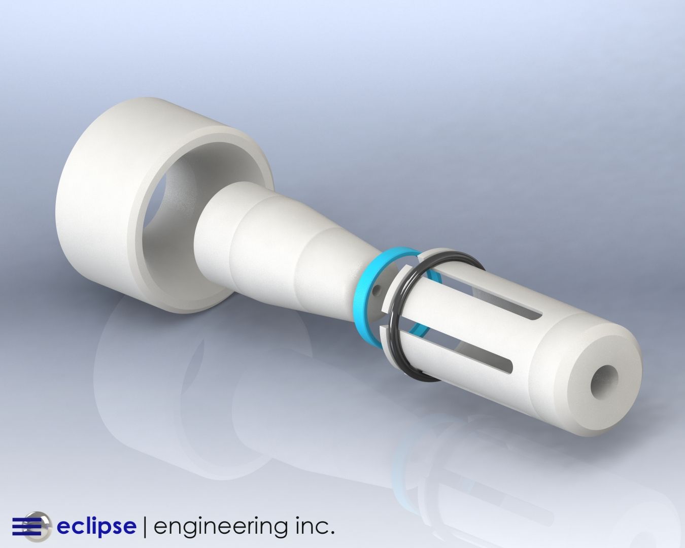
In dynamic applications, an O-ring is typically used to seal between a rod or piston and a cylinder wall.
Piston O-Ring:
An O-ring sits in a gland, or groove, which holds the O-ring in place while allowing flexible deformation as it is squeezed between a rod or piston and cylinder wall.
This compressive elasticity is necessary to provide a tight seal to exclude fluids or gases effectively.
What Causes O-Ring Extrusion?
O-ring seal extrusion is like a bicycle tire tube bulge — where part of the tube squeezes out through a crack in the tire, making the tube vulnerable to bursting.
Another example of extrusion, but intentional in this case, is squeezing glue out of a tube. As the glue gets older, it can dry out, becoming thicker and forming a crust that constricts the nozzle.
The thickness and constriction make it harder to squeeze the glue out, requiring more pressure.
This is the reverse of seal applications where we don’t want extrusion to happen.
Seal extrusion depends on:
- Pressure
- Softness/hardness of the material
- The clearance or gap through which it escapes
O-ring extrusion is more possible in applications where pressure exceeds 500 psi. To mitigate the risk, O-rings need to be sufficiently firm with a close enough clearance gap.
Hardness and elasticity
Like all seals, O-rings need to be sufficiently squeezable to create a good seal between hard surfaces (usually metal). They also need to be firm enough to avoid excessive deformation and extrusion.
There are two main ways to measure O-ring resistance to extrusion:
Modulus of Elasticity
The Modulus of Elasticity defines a material’s resistance to elastic deformation. This is calculated as the ratio of stress (force) over strain (movement) — measured by stretching samples on a Tensometer.
Stress (force) : Strain (movement)
This is usually defined at 100% elongation (double its original length). It can also be reported at other percentages of elongation where figures can be different due to non-linear properties.
Shore A Durometer
The Shore A Durometer scale defines material hardness as a figure from 0 (soft) to 100 (hard). This correlates to increasing Modulus of Elasticity.
Standard O-ring material hardness is about 70–75 on the Shore A scale. With special additives, O-rings can be manufactured for hardness of 90–95 Shore A for high-pressure applications.
In certain instances, just this change in durometer is enough to halt the o-ring extrusion.
Clearance
Piston/rod clearance from a cylinder wall can also be defined two ways:
Diametrical Clearance:
the total difference between the piston/rod diameter and the bore diameter.
Radial Clearance:
the gap between the piston/rod and the cylinder bore.
The greater the clearance, the more likely the o-ring will extrude through the gap for a given pressure and o-ring material hardness.
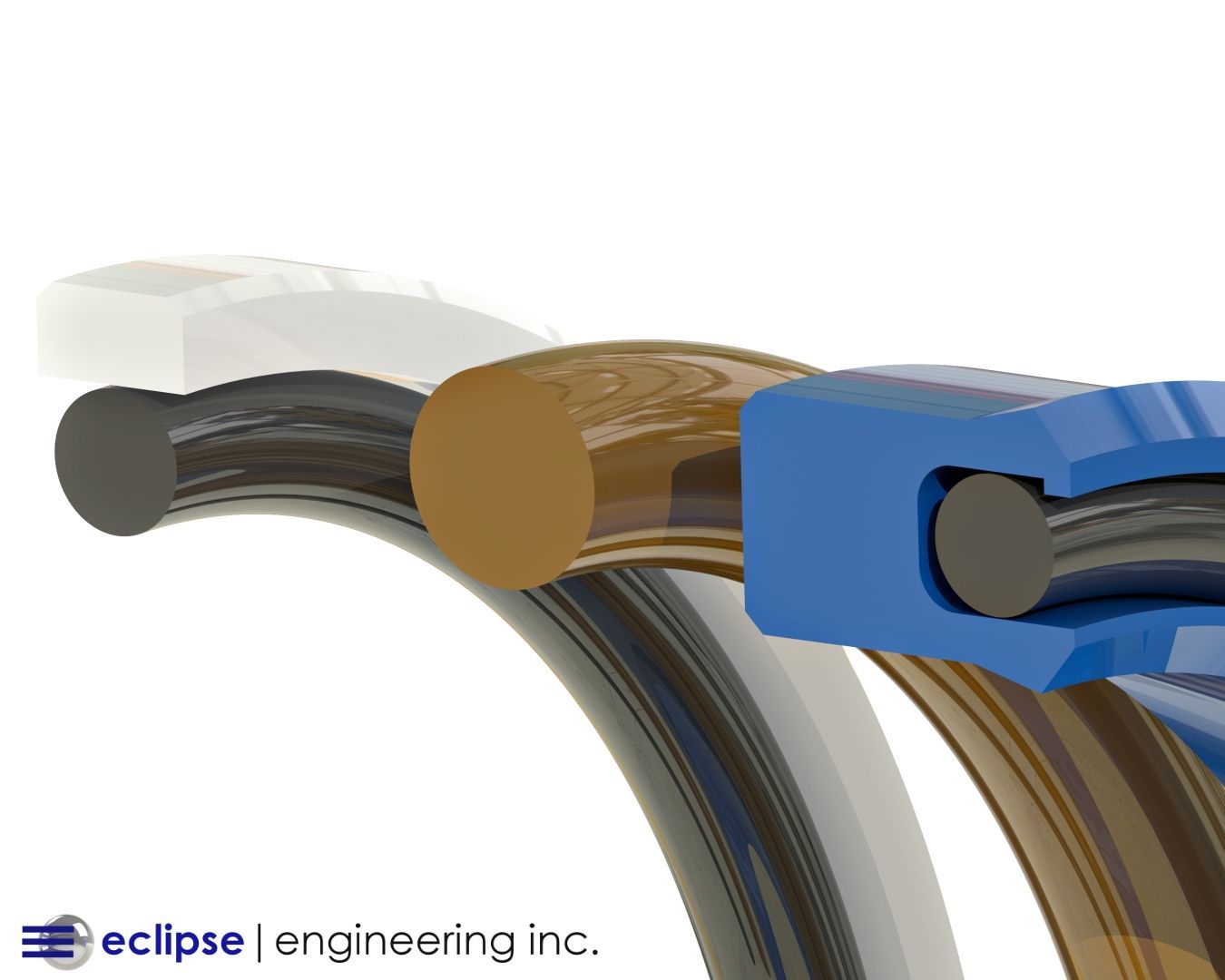
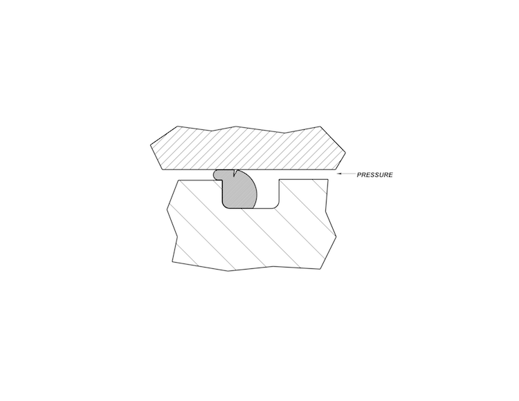
O-ring Large E-Gap Extrusion:
O-ring Small Gap Extrusion:
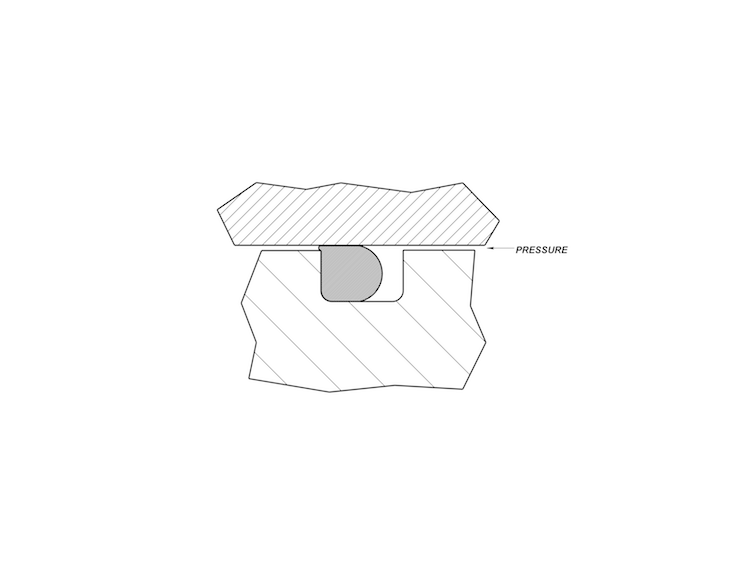
You can see how this works from the bicycle example above. The bigger the tire crack, the more likely the tube will squeeze through, and even more so as you pump the tire up with higher pressure.
Reducing piston or rod gap, for the same O-ring, can be an effective remedy for O-ring extrusion. You can get away with a softer O-ring or safely allow higher pressure fluids or gases in the application.
O-ring groove depth and width are also important for effective seal functioning but aren’t critical for extrusion mitigation.
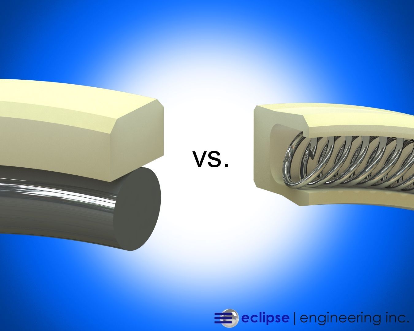
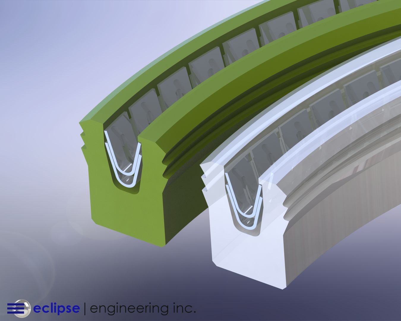
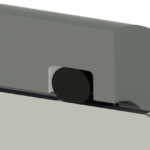
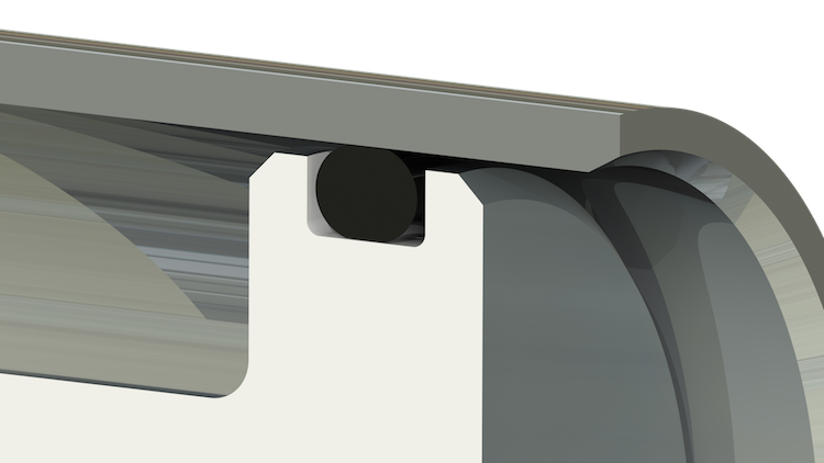
How Backup Rings Provide an Effective Solution
If an O-ring is close to extrusion because of unavoidable material softness/flexibility, pressure, or clearance gap, an effective fix is a backup ring on one or both sides of the O-ring.
Sufficient lateral room is required in the gland (slot) to accommodate the backup rings as well as the O-ring. If not, the gland needs to be re-designed.
Backup rings can take O-ring resilience to another level in demanding operating environments.
Find out more about Eclipse’s robust quality O-rings and backup rings to fit your application. Learn about the history of the O-ring >