How To Design The Perfect Seal For An Accumulator
An accumulator is an apparatus for storing energy or power. This is an obsolete term for a capacitor, which is commonly used in electrical engineering.
In hydraulic systems, we use accumulators for two very specific purposes:
- To store energy for use either in an emergency or to give a momentary surge of power due to the loss of the hydraulic system.
In an aircraft , for example, you could use an accumulator when you need to “blow down” the landing gear. A valve is opened to release the fluid into the landing gear system, forcing the gear into the down-and-locked position.
- The second use for an accumulator is to act as a shock absorber in a hydraulic system. Since hydraulic fluid is generally considered non-compressible, an accumulator can “smooth out the bumps.”
A good example of this is when a crane is slewing, and the operator wants to move the load very slowly without jerking it around. Hydraulic gear motors and pumps often create pulses that an accumulator will absorb and thereby not transfer those pulses to the load where a welder may be setting a beam on a building.
Common Types of Accumulators
There are two common accumulators:
- Bladder-style accumulator
- Piston-style accumulator
Both accumulator types use nitrogen gas as the energy-storing or shock-absorption method, but both work dramatically different.
Bladder Style Accumulator
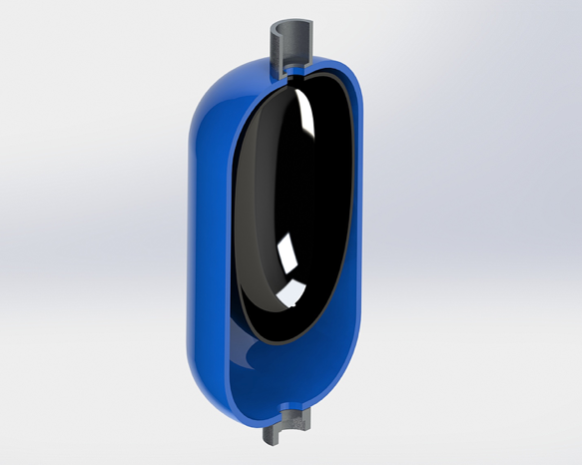
The bladder-style accumulator has a rubber bladder inside a rounded-chamber, with a Schrader valve sticking out of the chamber on one side.
The other side contains a type of hydraulic fitting arrangement, which allows you to connect a hydraulic line to the device. This style looks a little bit like a bomb to allow the rubber bladder to not crease within the device.
The bladder is normally filled with nitrogen gas. This pressure can vary depending on the application, but oftentimes sits between 500 and 1000 psi nitrogen gas.
Without hydraulic fluid in the system, the entire bladder fills the cavity. When a hydraulic source is attached and exceeds the pressure in the accumulator, the rubber bladder acts as a hydraulic spring, absorbing shock waves within the hydraulic system over the pressure of the static accumulator.
Uses of Bladder-Style Accumulators
Many homes use an accumulator in their water systems to stop “water hammer” — that clang you might hear when you shut the water valve too quickly. The accumulator absorbs that shock in water.
In the earlier example of a crane slewing, it’s the combination of the teeth in the gear motor and pump that cause the vibration felt at the end of the load. Oftentimes, some well-placed, high-pressure hoses in between all the rigid tubing in the hydraulic system will accomplish the same task the accumulator does.
Thus, the bladder-style accumulator is excellent for shock absorption.
Piston-Style Accumulators
The second common style of accumulator is the piston accumulator. This device is usually intended to store energy, and release that energy on-demand.
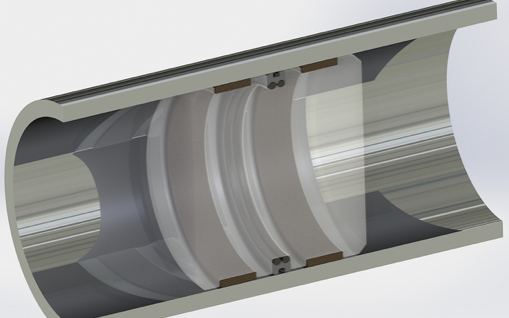
Because this is typically not a momentary device, the amount of energy is taken up by the displacement of a piston in a long tube where the “piston” is used to compress the nitrogen gas.
This compression causes the gas pressure to rise above the initial pressure, and thereby stores the energy until a valve is opened, allowing the compressed nitrogen gas to force the piston down the tube. This in turn forces the hydraulic fluid to move from the tube and exert energy.
Use of Piston-Style Accumulators
Calling back to the example we used earlier about needing to lower landing gear, the accumulator needs to have enough travel to move the stowed gear in the up-and-locked position into the down-and-locked position.
The length and diameter of the accumulator must at least match the volume necessary to extend the gear with a margin of safety. There also needs to be enough pressure from the system to cause the gear to lock into place at the bottom of the stroke.
Since the piston-style accumulator is a dynamic device, the piston will be required to move rapidly down the tube without scoring the tube. Unlike the bladder accumulator, the piston-style will require dynamic seals on the piston to allow it to maintain nitrogen pressure in a dynamic state without leaking the nitrogen to the hydraulic side.
This is a bit more complicated than the bladder, which is a single membrane.
The piston must be able to move quickly with low friction, and will generally requires some kind of rubber contact to hold the nitrogen gas from leaking into the hydraulic system.
Eclipse Accumulator Seals
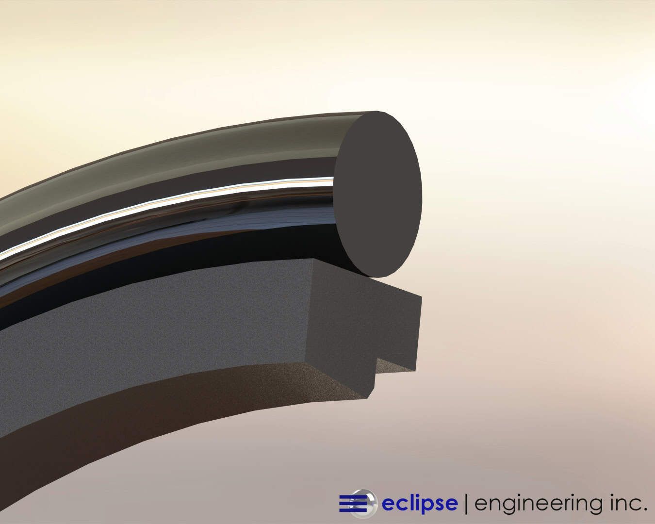
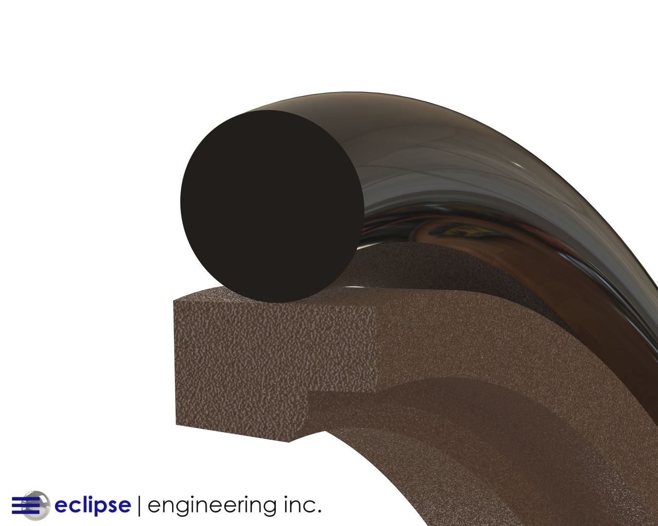
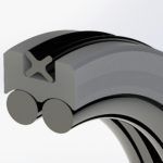
At Eclipse , our seal engineers design a “Q” seal that uses a Teflon element as the piston seal, with a combination of rubber energizers and an “X” ring in the middle of the Teflon piston seal to stop the flow of gas across to the hydraulic side.
This combination allows for rubber contact against the nitrogen. Nestling the X ring within the Teflon seal lowers the force of the X ring on the bore, keeping friction and heat to a minimum.
A set of Teflon wear rings on both sides of the Q seal allows the piston to “float” without scoring on the bore of the tube. There should be no side loading in this design, and keeping the piston centered in the bore protects the sealing surface against scratches which would allow the nitrogen to eventually leak out.
Eclipse Seals in Modern Day Aircraft
Like accumulators, another crucial hydraulic system seal can be found in aircraft. This system controls the brakes, suspension, flap actuators, landing gear, and more. These systems undergo extreme amounts of stress, especially during take-off and landing.
The types of custom seals our seal engineering specialists create for aircraft hydraulic systems are made of durable polytetrafluoroethylene, otherwise known as PTFE, or by its household name of Teflon.

