History Unlocked: A Look At The O-Ring

The mechanical O-ring is a very simple item, hidden from view in most applications and unappreciated by the millions who benefit from its use in the technologies that make much of modern life possible.
Since its humble beginnings in Sweden at the end of the 19th century, the O-ring has grown to become a ubiquitous and crucial mechanical seal component in a huge range of technology. O-rings are used in industrial machinery , farming equipment, cars, airplanes — even spacecraft.
Needless to say, with this unassuming little miracle, many of mankind’s achievements of the last century would have been impossible.
What Is An O-Ring?
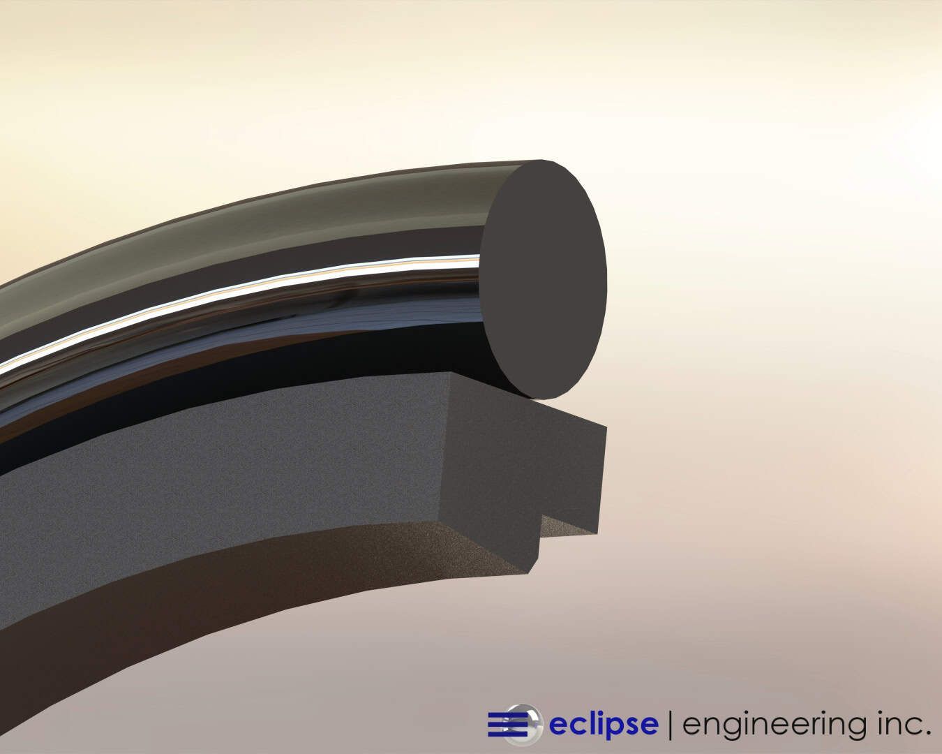
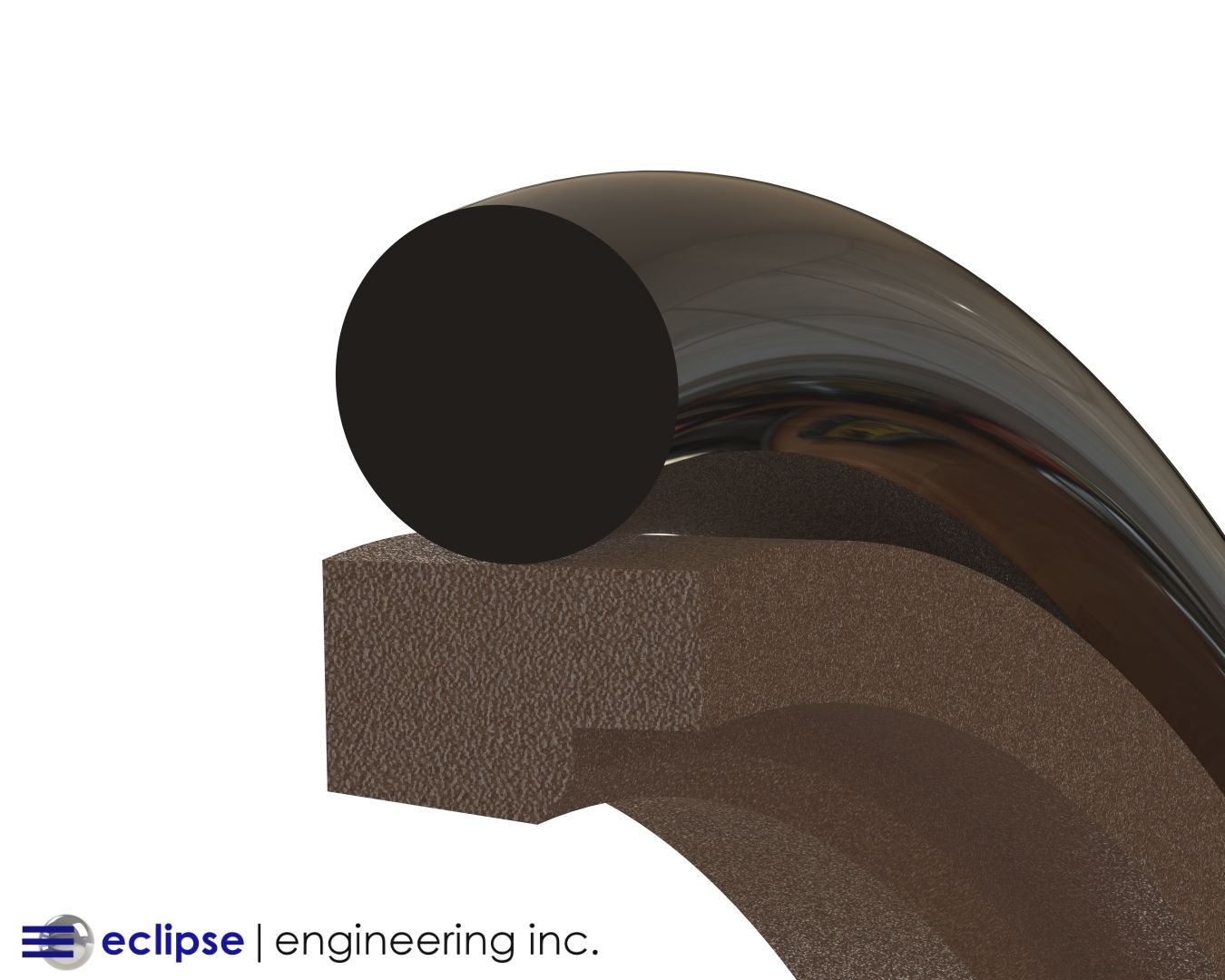
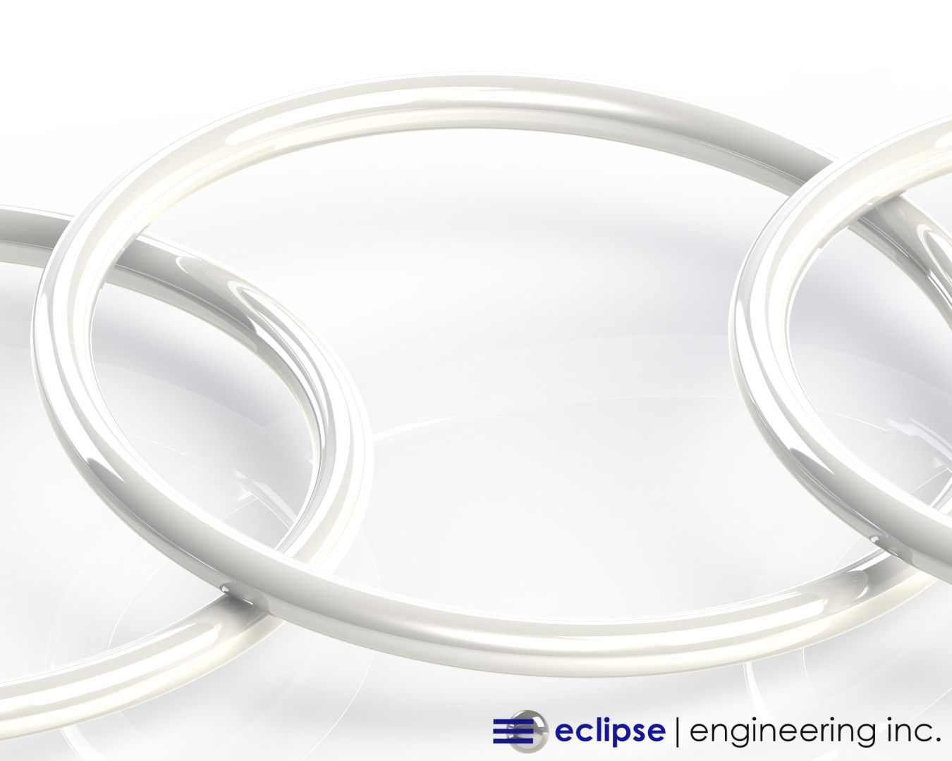
A mechanical O-ring is made of elastic polymer in the shape of a letter ‘O’. It provides a mechanical seal to contain liquids or gases. It typically sits in a groove, compressed between a piston and a cylinder.
It’s also used to seal static, or non-moving, circular joints between metal components.
The fundamental feature of modern O-rings is the material they’re made out of — rubber. That’s where our story begins.
How Rubber Became a Pillar of Civilization
Rubber as it’s found in nature was used by the Mayans and Aztecs for bouncy ball games, and was first used by Europeans as a pencil eraser around 1770. It then graduated to clothing and footwear.
However, a consistent problem encountered with the rubber of this time was that it was brittle and, when left in the sun, would gum up due to the heat.
A revolution came by way of accident in the year of 1840, when Charles Goodyear (recognize that last name?) stumbled upon vulcanization through use of a sulphur additive.
Vulcanization is a chemical process which alters the characteristics of rubber, vastly improving its capability to withstand heat and pressure. It’s less prone to swell, resists abrasion, has a higher tensile strength, and is more elastic across a wide range of temperatures.
This discovery greatly expanded rubber use during the Industrial Revolution. Suddenly, it was showing up everywhere, in everyday items such as tires, hoses, shoe soles, and fan belts.
Dependence on natural rubber ballooned over the next few decades. By World War II, the United States was consuming about half of the world’s supply of natural rubber.
A fighter plane at this time was built with 1,000 pounds of rubber. A battleship? 150,000 pounds.
There was one major problem, though — natural rubber was subject to supply problems. Plus, it wasn’t cheap.
Enter synthetic rubber. It had actually been invented years earlier, in 1909. By polymerizing methyl isoprene, a German team of researchers led by Fritz Hofmann was able to devise synthetic rubber.
But it wasn’t until the middle of the century that the overwhelming demand for rubber grew so much that eyes turned toward the synthetic option.
President Roosevelt set out to solve the problem by establishing a partnership with the country’s biggest rubber companies to mass-produce synthetic rubber Styrene, at twice the output of the world’s total natural rubber production before the war.
After the war, this development allowed rubber to become ever more pervasive in consumer and industrial products.
From the 1950s to the 70’s, rapid advances in synthetic polymers led to better and better variations on rubber, ultimately creating today’s high-performance elastomers.
Who Invented O-Rings?
The advances of O-rings run parallel to the improvements made in rubber technologies over the course of the 20th century.
The very first patent for the rubber O-ring was filed back in 1896 in Sweden, by J. O. Lundberg. He is credited as the original inventor, but unfortunately not much is known about him.
Meanwhile a machinist, Niels Christensen, immigrated to the US from Denmark in 1891, and filed his own U.S. patent in 1937 at the age of 72, about 40 years after Lundberg.
Soon after that, he also patented an air brake system for trams, but his intellectual property was passed from company to company, including Westinghouse, despite his legal efforts to maintain his rights. Eventually though, Christensen would receive compensation of $75,000 for his work on O-rings, with further payment to his heirs much later.
How The O-Ring Became Ubiquitous
The inauspicious birth of the O-ring stands in stark contrast to the star turn it took in World War II. It was at this time that the United States government commandeered the rubber O-ring patent as a piece of critical mechanical seal technology and gave manufacturing rights to various organizations.
This was right around the same time that FDR prioritized a nationwide pivot to synthetic rubbers. It turns out that O-rings and high-performing synthetic rubbers were a match made in heaven.
With the more elastic and durable properties of synthetic rubber aligned with the simple concept of a sealing ring, it was now possible to rely on O-rings to help automobiles stay on the road, planes in the air, and much more.
The O-Ring’s Infamous Role in The Challenger Explosion
After the tragic explosion of the Challenger space shuttle in 1986, physicist Richard Feynman famously demonstrated on television that the root cause was an O-ring failure, due to low temperature.
The extreme cold had caused the rubber o-ring to became rigid , losing pliability, and failed to seal a joint on a rocket booster, causing high temperature gases to blow-out. This led to a total structural failure and disintegration of the shuttle.
After the disaster, NASA scientists re-designed the rocket booster with an onboard heater, keeping the O-rings up to at least 10°C –– which fixed the problem for good.
A Transformation of Industry Standards
After the tragic destruction of the Challenger, a lot more was learned about O-ring material properties and limitations. And many more people realized just how much was being asked of such a simple invention.
The accident led to stricter documentation and regulation around O-rings. They were labeled with batch, date, and manufacturer information, allowing precise tracking and control of distribution –– much like products in the medical industry.
Aerospace and military sectors, who especially needed to ensure their o-rings never failed, went to even greater lengths. They used individually packaged o-rings with detailed material information, so they could easily be recalled or tested in case of failure.
These transformations increased the reliability of o-rings greatly, which is why we’re now able to use them widely in extremely sensitive applications.
Achieving Critical Quality In O-Rings
O-ring performance can mean the difference between success and crisis, as the Challenge episode illustrated. For this reason, they are commonly subjected to very stringent quality control procedures, with multiple rounds of quality and assurance and stress testing before release to users.
Eclipse Engineering supplies and supports O-rings from the best sources in the world, using resilient materials and rigorous manufacturing processes to ensure consistent and reliable operation — especially for high-stake applications in aerospace , pharmaceutical , and semiconductor industries , along with the food and beverage , energy , and automotive sectors.
Want to know more about our O-ring standards and supply sources? Contact us today »

