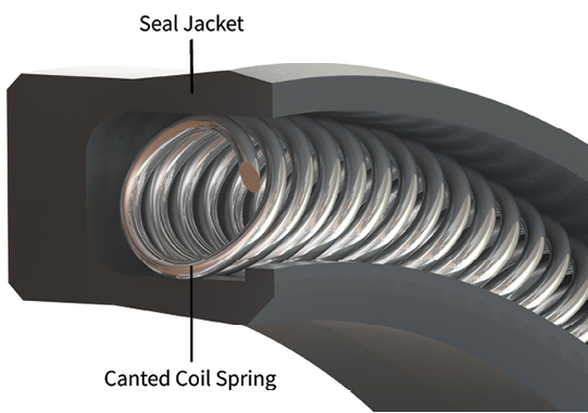
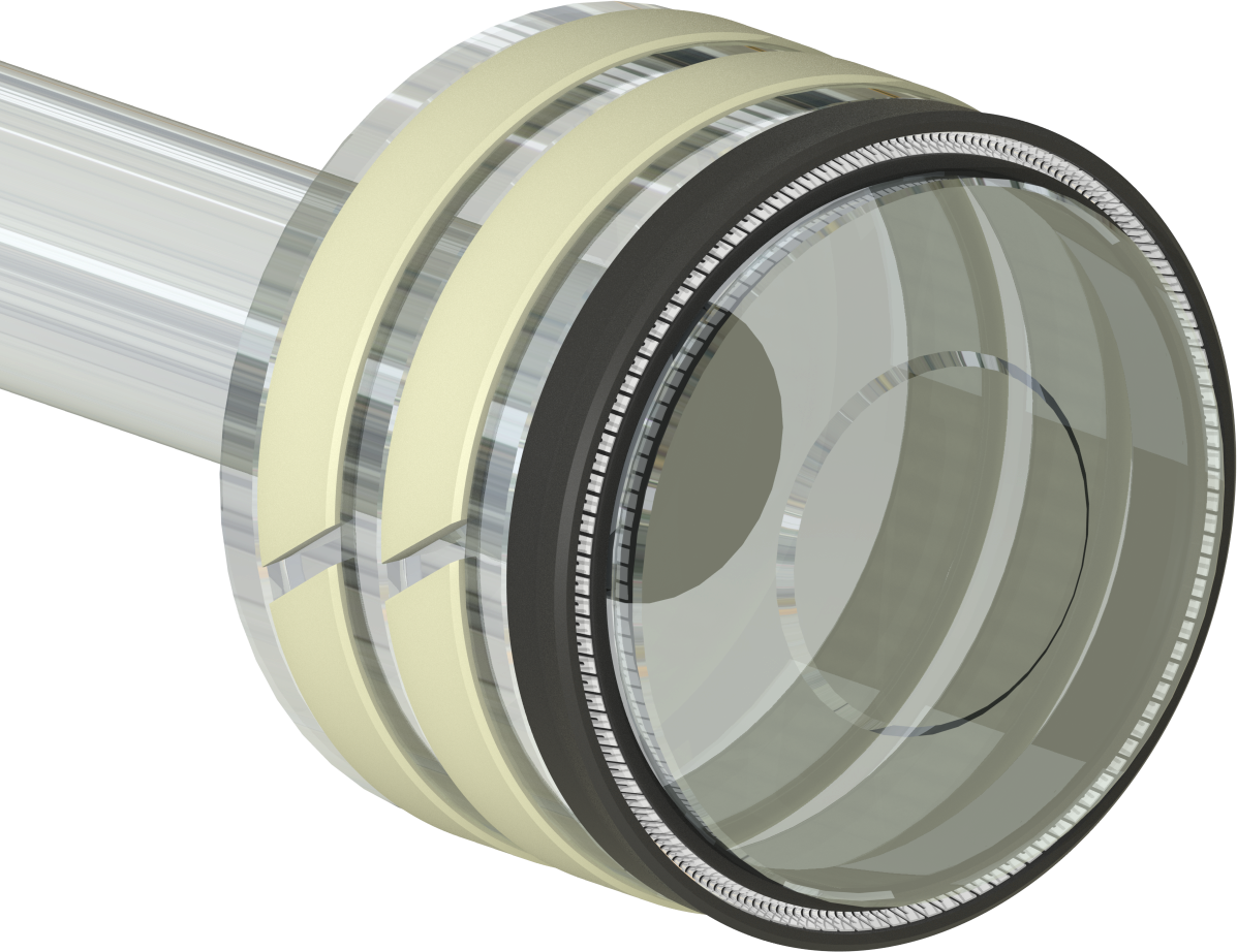
ECLIPSE ECS – CANTED COIL SPRING ENERGIZED PISTON SEAL
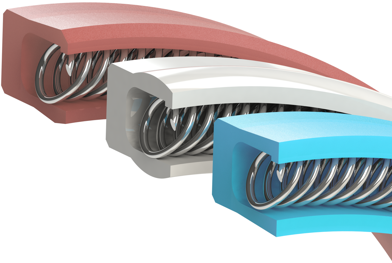
Eclipse Canted Coil Spring Seals employ a specialty wound wire spring installed in a polymer jacket. The canted coil is unique in the sealing industry because of its semi-linear load curve. As an engineered loading device, canted coil springs display a very constant load over a large deflection range. This feature allows
Canted Coil Spring Seals to operate in friction sensitive applications like HPLC, encoders and flap actuators with consistent performance. Seals used in battery operated devices utilize these seals – minimizing seal friction and optimizing battery life. On the other end of the spectrum, Canted Coil Spring Seals are used with heavy load springs for use in highly viscous media such as epoxies and urethanes. Eclipse maintains an extensive inventory of canted coil spring making it possible to tailor seal requirements to nearly any application.
Typical Range of Application
Pressure
Vacuum to 3,000 psi
[0 to 200 bar]
Temperature*
-320°F to 450°F
[-195°C to 230°C]
Ratings will vary based on materials and operating conditions
*Limited by O-Ring compound
Values and ratings in this catalog are based on industry standard applications operating under ideal conditions. The customer should assume responsiblity for validation testing of performance and suitabilty of Eclipse Engineering products.
Eclipse Engineering accepts no liabilty for the accuracy and applicabilty of provided information.
STANDARD ORDERING EXAMPLE:
ECS-P-234-LW-ET006-M-S
| ECS | = Seal Series | |
| P | = Piston | |
| 234 | = Dash Number | |
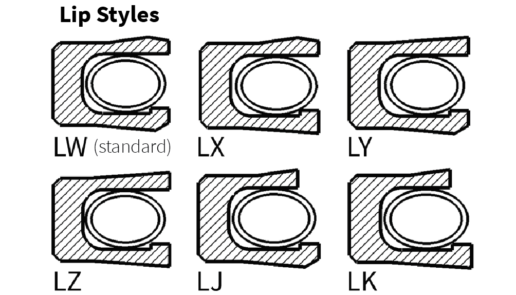
| LW | = Lip Style | |
| ET006 | = Seal Material Code | |
| M | = Spring Load L – Light M – Medium H – Heavy | |
| S | = Spring Material S – Stainless Steel E – Elgiloy® H – Hastelloy® | |
NON-STANDARD ORDERING EXAMPLE:
ECS-P-C-02953-LW-ET006-M-S
C
= Nominal Cross-Section
A = 1/16 in. (000 Series)
B = 3/32 in. (100 Series)
C = 1/8 in. (200 Series)
D = 3/16 in. (300 Series)
E = 1/4 in. (400 Series)
02953
= Bore Diameter in 1000ths
Example: 02953 = Ø2.953 [75MM] Rod Diameter
ECS STANDARD SEAL MATERIALS
| ECLIPSE MATERIAL CODE | DESCRIPTION | COLOR | APPLICATIONS |
|---|---|---|---|
| ET000 | Virgin PTFE | White | Light Duty / Static / Cryogenics |
| ET006 | Carbon filled PTFE | Black | General Purpose |
| EU000 | Virgin UHMWPE | Translucent White | Viscous Media / Water |
| ET014 | Polyimide filled PTFE | Orange/Brown | High Sealabilty / Soft Hardware |
See Eclipse Material Guide for complete list of available materials.
ECS STANDARD SPRING MATERIALS
| ECLIPSE MATERIAL CODE | SPRING MATERIAL | APPLICATION |
|---|---|---|
| S | 300 Series Stainless Steel | General purpose, standard spring material |
| E | Elgiloy® | Improved performance and corrosion resistance; NACE approved |
| H | Hastelloy® C276 | Maximum chemical/corrosion resistance |
STANDARD DASH NUMBERS
000 SERIES:
| GLAND TOLERANCES | ||
|---|---|---|
| SEAL ID | ØA | ØB |
| 0.125 to 0.374 | +0.000
-0.001 |
+0.001
-0.000 |
| 0.375 to 2.999 | +0.000
-0.002 |
+0.002
-0.000 |
| 3.000 to 7.999 | +0.000
-0.003 |
+0.003
-0.000 |
| 8.000 and up | +0.000
-0.004 |
+0.004
-0.000 |
| 000 SERIES MAXIMUM EXTRUSION GAP (E), AT 70° F | |||
|---|---|---|---|
| 300 psi | 1500 psi | 3000 psi | 6000 psi |
| 0.008 | 0.004 | 0.003 | 0.002 |
Consult Eclipse Engineering for all custom or unlisted sizes.

000 SERIES STANDARD DASH NUMBERS:
| DASH # | A | B |
|---|---|---|
| 006 | 0.125 | 0.250 |
| 007 | 0.156 | 0.281 |
| 008 | 0.187 | 0.312 |
| 009 | 0.218 | 0.343 |
| 010 | 0.250 | 0.375 |
| 011 | 0.312 | 0.437 |
| 012 | 0.375 | 0.500 |
| 013 | 0.437 | 0.562 |
| 014 | 0.500 | 0.625 |
| 015 | 0.562 | 0.687 |
| 016 | 0.625 | 0.750 |
| 017 | 0.687 | 0.812 |
| 018 | 0.750 | 0.875 |
| 019 | 0.812 | 0.937 |
| 020 | 0.875 | 1.000 |
| 021 | 0.937 | 1.062 |
| 022 | 1.000 | 1.125 |
| 023 | 1.062 | 1.187 |
| 024 | 1.125 | 1.250 |
| 025 | 1.187 | 1.312 |
| 026 | 1.250 | 1.375 |
| 027 | 1.312 | 1.437 |
| 028 | 1.375 | 1.500 |
| 029 | 1.500 | 1.625 |
| 030 | 1.625 | 1.750 |
| 031 | 1.750 | 1.875 |
| 032 | 1.875 | 2.000 |
| 033 | 2.000 | 2.125 |
| 034 | 2.125 | 2.250 |
| 035 | 2.250 | 2.375 |
| 036 | 2.375 | 2.500 |
| 037 | 2.500 | 2.625 |
| 038 | 2.625 | 2.750 |
| 039 | 2.750 | 2.875 |
| 040 | 2.875 | 3.000 |
| 041 | 3.000 | 3.125 |
| 042 | 3.250 | 3.375 |
| 043 | 3.500 | 3.625 |
| 044 | 3.750 | 3.875 |
| 045 | 4.000 | 4.125 |
Consult Eclipse Engineering for all custom or unlisted sizes.
100 SERIES STANDARD DASH NUMBERS
| GLAND TOLERANCES | ||
|---|---|---|
| SEAL ID | ØA | ØB |
| 0.125 to 0.374 | +0.000
-0.001 |
+0.001
-0.000 |
| 0.375 to 2.999 | +0.000
-0.002 |
+0.002
-0.000 |
| 3.000 to 7.999 | +0.000
-0.003 |
+0.003
-0.000 |
| 8.000 and up | +0.000
-0.004 |
+0.004
-0.000 |
| 100 SERIES MAXIMUM EXTRUSION GAP (E), AT 70° F | |||
|---|---|---|---|
| 300 psi | 1500 psi | 3000 psi | 6000 psi |
| 0.010 | 0.006 | 0.004 | 0.003 |
Consult Eclipse Engineering for all custom or unlisted sizes.
100 SERIES STANDARD DASH NUMBERS:
| DASH # | A | B |
|---|---|---|
| 106 | 0.187 | 0.375 |
| 107 | 0.219 | 0.406 |
| 108 | 0.250 | 0.437 |
| 109 | 0.312 | 0.500 |
| 110 | 0.375 | 0.562 |
| 111 | 0.437 | 0.625 |
| 112 | 0.500 | 0.687 |
| 113 | 0.562 | 0.750 |
| 114 | 0.625 | 0.812 |
| 115 | 0.687 | 0.875 |
| 116 | 0.750 | 0.937 |
| 117 | 0.812 | 1.000 |
| 118 | 0.875 | 1.062 |
| 119 | 0.937 | 1.125 |
| 120 | 1.000 | 1.187 |
| 121 | 1.062 | 1.250 |
| 122 | 1.125 | 1.312 |
| 123 | 1.187 | 1.375 |
| 124 | 1.250 | 1.437 |
| 125 | 1.312 | 1.500 |
| 126 | 1.375 | 1.562 |
| 127 | 1.437 | 1.625 |
| 128 | 1.500 | 1.687 |
| 129 | 1.562 | 1.750 |
| 130 | 1.625 | 1.812 |
| 131 | 1.687 | 1.875 |
| 132 | 1.750 | 1.937 |
| 133 | 1.812 | 2.000 |
| 134 | 1.875 | 2.062 |
| 135 | 1.937 | 2.125 |
| 136 | 2.000 | 2.187 |
| 137 | 2.062 | 2.250 |
| 138 | 2.125 | 2.312 |
| 139 | 2.187 | 2.375 |
| 140 | 2.250 | 2.437 |
| 141 | 2.312 | 2.500 |
| 142 | 2.375 | 2.562 |
| 143 | 2.437 | 2.625 |
| 144 | 2.500 | 2.687 |
| 145 | 2.562 | 2.750 |
| 146 | 2.625 | 2.812 |
| 147 | 2.687 | 2.875 |
| 148 | 2.750 | 2.937 |
| 149 | 2.812 | 3.000 |
| 150 | 2.875 | 3.062 |
| 151 | 3.000 | 3.187 |
| 152 | 3.250 | 3.437 |
| 153 | 3.500 | 3.687 |
| 154 | 3.750 | 3.937 |
| 155 | 4.000 | 4.187 |
| 156 | 4.250 | 4.437 |
| 157 | 4.500 | 4.687 |
| 158 | 4.750 | 4.937 |
| 159 | 5.000 | 5.187 |
| 160 | 5.250 | 5.437 |
| 161 | 5.500 | 5.687 |
Consult Eclipse Engineering for all custom or unlisted sizes.
200 SERIES STANDARD DASH NUMBERS
| GLAND TOLERANCES | ||
|---|---|---|
| SEAL ID | ØA | ØB |
| 0.125 to 0.374 | +0.000
-0.001 |
+0.001
-0.000 |
| 0.375 to 2.999 | +0.000
-0.002 |
+0.002
-0.000 |
| 3.000 to 7.999 | +0.000
-0.003 |
+0.003
-0.000 |
| 8.000 and up | +0.000
-0.004 |
+0.004
-0.000 |
| 200 SERIES MAXIMUM EXTRUSION GAP (E), AT 70° F | |||
|---|---|---|---|
| 300 psi | 1500 psi | 3000 psi | 6000 psi |
| 0.014 | 0.008 | 0.006 | 0.003 |
Consult Eclipse Engineering for all custom or unlisted sizes.

200 SERIES STANDARD DASH NUMBERS:
| DASH # | A | B |
|---|---|---|
| 202 | 0.250 | 0.500 |
| 204 | 0.375 | 0.625 |
| 206 | 0.500 | 0.750 |
| 208 | 0.625 | 0.875 |
| 209 | 0.687 | 0.937 |
| 210 | 0.750 | 1.000 |
| 211 | 0.812 | 1.062 |
| 212 | 0.875 | 1.125 |
| 213 | 0.937 | 1.187 |
| 214 | 1.000 | 1.250 |
| 215 | 1.062 | 1.312 |
| 216 | 1.125 | 1.375 |
| 217 | 1.187 | 1.437 |
| 218 | 1.250 | 1.500 |
| 219 | 1.312 | 1.562 |
| 220 | 1.375 | 1.625 |
| 221 | 1.437 | 1.687 |
| 222 | 1.500 | 1.750 |
| 223 | 1.625 | 1.875 |
| 224 | 1.750 | 2.000 |
| 225 | 1.875 | 2.125 |
| 226 | 2.000 | 2.250 |
| 227 | 2.125 | 2.375 |
| 228 | 2.250 | 2.500 |
| 229 | 2.375 | 2.625 |
| 230 | 2.500 | 2.750 |
| 231 | 2.625 | 2.875 |
| 232 | 2.750 | 3.000 |
| 233 | 2.875 | 3.125 |
| 234 | 3.000 | 3.250 |
| 235 | 3.125 | 3.375 |
| 236 | 3.250 | 3.500 |
| 237 | 3.375 | 3.625 |
| 238 | 3.500 | 3.750 |
| 239 | 3.625 | 3.875 |
| 240 | 3.750 | 4.000 |
| 241 | 3.875 | 4.125 |
| 242 | 4.000 | 4.250 |
| 243 | 4.125 | 4.375 |
| 244 | 4.250 | 4.500 |
| 245 | 4.375 | 4.625 |
| 246 | 4.500 | 4.750 |
| 247 | 4.625 | 4.875 |
| 248 | 4.750 | 5.000 |
| 249 | 4.875 | 5.125 |
| 250 | 5.000 | 5.250 |
| 252 | 5.250 | 5.500 |
| 254 | 5.500 | 5.750 |
| 256 | 5.750 | 6.000 |
| 258 | 6.000 | 6.250 |
| 260 | 6.500 | 6.750 |
| 262 | 7.000 | 7.250 |
| 264 | 7.500 | 7.750 |
| 266 | 8.000 | 8.250 |
| 268 | 8.500 | 8.750 |
| 270 | 9.000 | 9.250 |
Consult Eclipse Engineering for all custom or unlisted sizes.
300 SERIES STANDARD DASH NUMBERS
| GLAND TOLERANCES | ||
|---|---|---|
| SEAL ID | ØA | ØB |
| 0.125 to 0.374 | +0.000
-0.001 |
+0.001
-0.000 |
| 0.375 to 2.999 | +0.000
-0.002 |
+0.002
-0.000 |
| 3.000 to 7.999 | +0.000
-0.003 |
+0.003
-0.000 |
| 8.000 and up | +0.000
-0.004 |
+0.004
-0.000 |
| 300 SERIES MAXIMUM EXTRUSION GAP (E), AT 70° F | |||
|---|---|---|---|
| 300 psi | 1500 psi | 3000 psi | 6000 psi |
| 0.020 | 0.010 | 0.008 | 0.004 |
Consult Eclipse Engineering for all custom or unlisted sizes.

300 SERIES STANDARD DASH NUMBERS
| DASH # | A | B |
|---|---|---|
| 316 | 0.875 | 1.250 |
| 317 | 0.937 | 1.312 |
| 318 | 1.000 | 1.375 |
| 319 | 1.062 | 1.437 |
| 320 | 1.125 | 1.500 |
| 321 | 1.187 | 1.562 |
| 322 | 1.250 | 1.625 |
| 323 | 1.312 | 1.687 |
| 324 | 1.375 | 1.750 |
| 325 | 1.500 | 1.875 |
| 326 | 1.625 | 2.000 |
| 327 | 1.750 | 2.125 |
| 328 | 1.875 | 2.250 |
| 329 | 2.000 | 2.375 |
| 330 | 2.125 | 2.500 |
| 331 | 2.250 | 2.625 |
| 332 | 2.375 | 2.750 |
| 333 | 2.500 | 2.875 |
| 334 | 2.625 | 3.000 |
| 335 | 2.750 | 3.125 |
| 336 | 2.875 | 3.250 |
| 337 | 3.000 | 3.375 |
| 338 | 3.125 | 3.500 |
| 339 | 3.250 | 3.625 |
| 340 | 3.375 | 3.750 |
| 341 | 3.500 | 3.875 |
| 342 | 3.625 | 4.000 |
| 343 | 3.750 | 4.125 |
| 344 | 3.875 | 4.250 |
| 345 | 4.000 | 4.375 |
| 346 | 4.125 | 4.500 |
| 347 | 4.250 | 4.625 |
| 348 | 4.375 | 4.750 |
| 349 | 4.500 | 4.875 |
| 350 | 4.625 | 5.000 |
| 351 | 4.750 | 5.125 |
| 352 | 4.875 | 5.250 |
| 353 | 5.000 | 5.375 |
| 354 | 5.125 | 5.500 |
| 355 | 5.250 | 5.625 |
| 356 | 5.375 | 5.750 |
| 357 | 5.500 | 5.875 |
| 358 | 5.625 | 6.000 |
| 359 | 5.750 | 6.125 |
| 360 | 5.875 | 6.250 |
| 361 | 6.000 | 6.375 |
| 362 | 6.250 | 6.625 |
| 363 | 6.500 | 6.875 |
| 365 | 7.000 | 7.375 |
| 367 | 7.500 | 7.875 |
| 369 | 8.000 | 8.375 |
| 371 | 8.500 | 8.875 |
| 373 | 9.000 | 9.375 |
| 375 | 9.500 | 9.875 |
| 377 | 10.000 | 10.375 |
| 378 | 10.500 | 10.875 |
Consult Eclipse Engineering for all custom or unlisted sizes.
400 SERIES STANDARD DASH NUMBERS
| GLAND TOLERANCES | ||
|---|---|---|
| SEAL ID | ØA | ØB |
| 0.125 to 0.374 | +0.000
-0.001 |
+0.001
-0.000 |
| 0.375 to 2.999 | +0.000
-0.002 |
+0.002
-0.000 |
| 3.000 to 7.999 | +0.000
-0.003 |
+0.003
-0.000 |
| 8.000 and up | +0.000
-0.004 |
+0.004
-0.000 |
| 400 SERIES MAXIMUM EXTRUSION GAP (E), AT 70° F | |||
|---|---|---|---|
| 300 psi | 1500 psi | 3000 psi | 6000 psi |
| 0.024 | 0.012 | 0.010 | 0.005 |
Consult Eclipse Engineering for all custom or unlisted sizes.
400 SERIES STANDARD DASH NUMBERS:
| DASH # | A | B |
|---|---|---|
| 401 | 1.500 | 2.000 |
| 402 | 1.625 | 2.125 |
| 403 | 1.750 | 2.250 |
| 404 | 1.875 | 2.375 |
| 405 | 2.000 | 2.500 |
| 406 | 2.125 | 2.625 |
| 407 | 2.250 | 2.750 |
| 408 | 2.375 | 2.875 |
| 409 | 2.500 | 3.000 |
| 410 | 2.625 | 3.125 |
| 411 | 2.750 | 3.250 |
| 412 | 2.875 | 3.375 |
| 413 | 3.000 | 3.500 |
| 414 | 3.125 | 3.625 |
| 415 | 3.250 | 3.750 |
| 416 | 3.375 | 3.875 |
| 417 | 3.500 | 4.000 |
| 418 | 3.625 | 4.125 |
| 419 | 3.750 | 4.250 |
| 420 | 3.875 | 4.375 |
| 421 | 4.000 | 4.500 |
| 422 | 4.125 | 4.625 |
| 423 | 4.250 | 4.750 |
| 424 | 4.375 | 4.875 |
| 425 | 4.500 | 5.000 |
| 426 | 4.625 | 5.125 |
| 427 | 4.750 | 5.250 |
| 428 | 4.875 | 5.375 |
| 429 | 5.000 | 5.500 |
| 430 | 5.125 | 5.625 |
| 431 | 5.250 | 5.750 |
| 432 | 5.375 | 5.875 |
| 433 | 5.500 | 6.000 |
| 434 | 5.625 | 6.125 |
| 435 | 5.750 | 6.250 |
| 436 | 5.875 | 6.375 |
| 437 | 6.000 | 6.500 |
| 438 | 6.250 | 6.750 |
| 439 | 6.500 | 7.000 |
| 440 | 6.750 | 7.250 |
| 441 | 7.000 | 7.500 |
| 442 | 7.250 | 7.750 |
| 443 | 7.500 | 8.000 |
| 444 | 7.750 | 8.250 |
| 445 | 8.000 | 8.500 |
| 446 | 8.500 | 9.000 |
| 447 | 9.000 | 9.500 |
| 448 | 9.500 | 10.000 |
| 449 | 10.000 | 10.500 |
| 450 | 10.500 | 11.000 |
| 451 | 11.000 | 11.500 |
| 452 | 11.500 | 12.000 |
| 454 | 12.500 | 13.000 |
| 456 | 13.500 | 14.000 |
| 458 | 14.500 | 15.000 |
| 460 | 15.500 | 16.000 |
Consult Eclipse Engineering for all custom or unlisted sizes.
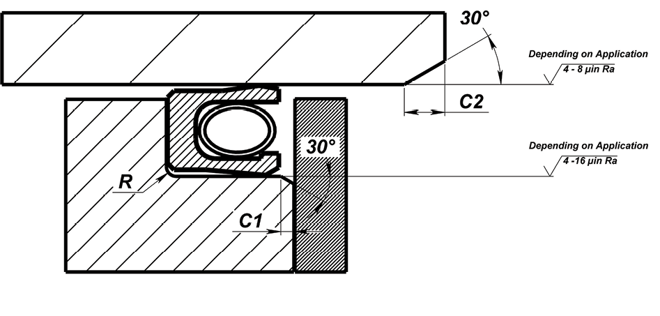
HARDWARE DETAILS – SPLIT GLAND
| SERIES | R
RADIUS MAX |
C1
CHAMFER MIN |
C2
CHAMFER MIN |
|---|---|---|---|
| 000 | 0.010 | 0.010 | 0.031 |
| 100 | 0.015 | 0.015 | 0.050 |
| 200 | 0.015 | 0.015 | 0.062 |
| 300 | 0.015 | 0.020 | 0.093 |
| 400 | 0.020 | 0.020 | 0.125 |
Consult Eclipse Engineering for application/material specific design requirements or for use in solid or non-standard glands.
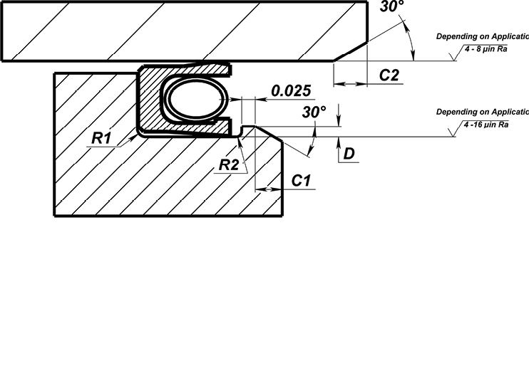
HARDWARE DETAILS – STEPPED GLAND
| SERIES | 0 | 100 | 200 | 300 | 400 |
|---|---|---|---|---|---|
| R1 Radius MAX | 0.010 | 0.015 | 0.015 | 0.015 | 0.020 |
| R2 Radius MAX | 0.005 | 0.005 | 0.007 | 0.010 | 0.010 |
| D Step Height | 0.008/0.012 | 0.010/0.015 | 0.015/0.020 | 0.017/0.023 | 0.022/0.028 |
| C1 Chamfer MIN | 0.025 | 0.030 | 0.040 | 0.045 | 0.055 |
| C2 Chamfer MIN | 0.031 | 0.050 | 0.062 | 0.093 | 0.125 |
| MIN BORE Ø required | 0.500 | 0.750 | 1.250 | 1.750 | 3.000 |
Consult Eclipse Engineering for application/material specific design requirements or for use in solid or non-standard glands.
"We started Eclipse with the premise that if we could solve enough of our customers problems they would continue to come back to us for solutions regardless of the type of products we offered."
What Can We Help You With?
Start a project request form and give us the specifics of your project. Our team will review and be in touch with you shortly!